Self-contained actuator subassembly for a rocker switch and rocker switch employing the same

a self-contained actuator and rocker switch technology, applied in the direction of tumbler/rocker switch, electrical apparatus, contact mechanism, etc., can solve the problem of inability to achiev

Active Publication Date: 2006-04-11
EATON INTELLIGENT POWER LTD
View PDF16 Cites 37 Cited by
  • Summary
  • Abstract
  • Description
  • Claims
  • Application Information

AI Technical Summary

Problems solved by technology

However, this is a costly and complicated endeavor and, in many instances, it cannot be accomplished without entirely disassembling the product and replacing the entire rocker switch 2.

Method used


Image

  • Self-contained actuator subassembly for a rocker switch and rocker switch employing the same
  • Self-contained actuator subassembly for a rocker switch and rocker switch employing the same
  • Self-contained actuator subassembly for a rocker switch and rocker switch employing the same

Examples


Embodiment Construction

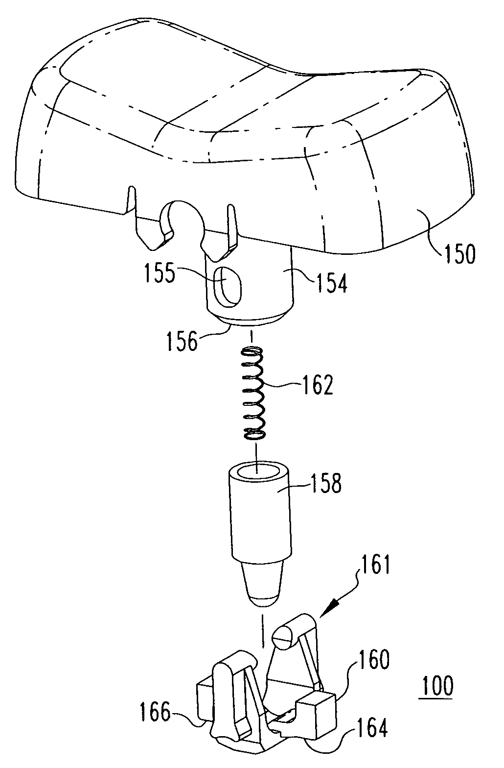
[0031]For purposes of illustration, the invention will be described as applied to rocker switches, although it will become apparent that it could also be applied to other types of electrical switching apparatus (e.g., without limitation, toggle switches) having an external operating member.

[0032]As employed herein, the term “fastener” refers to any suitable connecting or tightening mechanism expressly including, but not limited to, screws, bolts and the combinations of bolts and nuts (e.g., without limitation, lock nuts) and bolts, washers and nuts.

[0033]As employed herein, the statement that two or more parts are “coupled” together shall mean that the parts are joined together either directly or joined through one or more intermediate parts.

[0034]As employed herein, the term “operating characteristics” refers to the features of a rocker switch, expressly including, but not limited to, the type of operating member, the number of positions of the operating member, the location of pos...


PUM


Abstract

An actuator subassembly is for a rocker switch. The actuator subassembly forms a self-contained unit removably inserted within the rocker switch to define the operating characteristics thereof. The actuator subassembly includes an operating member operable between a plurality of positions, an extension and a spring-biased plunger. A shaped member which is pivotally coupled to the operating member includes a plurality of shaped sections each corresponding to one of the positions of the operating member. Each shaped section has a profile which is designed to provide the desired rocker switch operating characteristics, such as the type of action of the operating member and the operating force for the operating member.

Description

BACKGROUND OF THE INVENTION[0001]1. Field of the Invention[0002]The present invention relates generally to electrical switching apparatus and, more particularly, to actuator subassemblies for rocker switches. The invention also relates to rocker switches including actuator subassemblies.[0003]2. Background Information[0004]Rocker switches are generally old and well known in the art. As shown in FIG. 1, a rocker switch 2 generally includes a housing 4 and an actuator, such as the pivotal button or operating member 6, shown, which can be actuated from the exterior of the housing 4. The housing 4 is typically made from a non-conductive material, such as a heat-resistant plastic, and is structured to define a cavity 8. At the base 10 of the housing 4 are a plurality of terminals (e.g., the rocker switch 2 of FIG. 1 has first, second and third terminals 12, 14, 16). Typically, the first and third terminals 12, 16 are load terminals and the second or middle terminal 14 is the line termina...

Claims


Application Information

Patent Timeline
Patent Type & Authority Patents(United States)
IPC IPC(8): H01H13/00H01H3/00
CPCH01H23/205H01H23/168
Inventor LEE, DAVIN R.
Owner EATON INTELLIGENT POWER LTD
Why Eureka
Try Eureka