Defibrillation system and method designed for rapid attachment

a defibrillator and fast technology, applied in the field of defibrillators, can solve the problems of electrode deterioration, fibers within the heart to contract in unsynchronized ways, and the heart cannot pump blood effectively, and achieve the effect of quick and accurate application of defibrillator shocks

Inactive Publication Date: 2006-04-11
KONINKLIJKE PHILIPS ELECTRONICS NV
View PDF5 Cites 137 Cited by
  • Summary
  • Abstract
  • Description
  • Claims
  • Application Information

AI Technical Summary

Benefits of technology

[0008]The present invention is directed to a method and system for quickly and accurately applying the defibrillating shock to a victim of sudden cardiac arrest.

Problems solved by technology

During VF, the heart cannot pump blood effectively as it causes the individual muscle fibers within the heart to contract in an unsynchronized way.
Electrodes tend to deteriorate in time; thus, it is necessary to know their operating condition when they are used in a life-threatening situation.
Prior to use, an impedance is measured through the release layer disposed between a pair of electrodes; if the measurement is higher than the threshold impedance, the electrode is considered to be damaged, deteriorated, unfit for use.
A main drawback of the conventional AED 10 is that it requires time-consuming steps in the deployment and use of a defibrillator.
In a highly stressful emergency situation, inexperienced or infrequent operators of the AED 10 are often reluctant or do not aggressively destroy the clothing on an unconscious stranger to expose the recommended attachment areas, and further slow the rescue attempt.
In addition, some victims of cardiac arrest require removal of chest hair with a razor 6 to gain access to the attachment areas, which further delays the life-saving shock treatment, thus delaying and reducing the chances of a successful rescue attempt.
Moreover, even after gaining access to and attaching the defibrillation electrodes 12 by the trained rescuers of the AED 10, the delivery of the defibrillation shock often fails because the rescuers inadvertently fail to apply the electrode pads correctly, thus missing the heart.
The placement of the electrodes is then repeated, which is undesirable in the course of administering the defibrillating shock

Method used


Image

  • Defibrillation system and method designed for rapid attachment
  • Defibrillation system and method designed for rapid attachment
  • Defibrillation system and method designed for rapid attachment

Examples


Embodiment Construction

[0022]In the following description, for purposes of explanation rather than limitation, specific details are set forth such as the particular architecture, interfaces, techniques, etc., in order to provide a thorough understanding of the present invention. For purposes of simplicity and clarity, detailed descriptions of well-known devices, circuits, and methods are omitted so as not to obscure the description of the present invention with unnecessary detail.

[0023]Now, a description will be made in detail in regards to this invention with reference to the drawings.

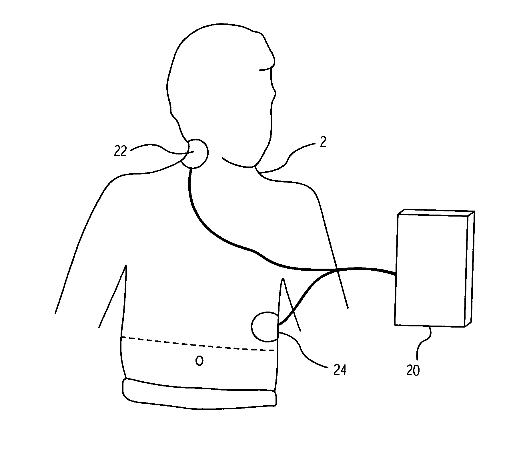
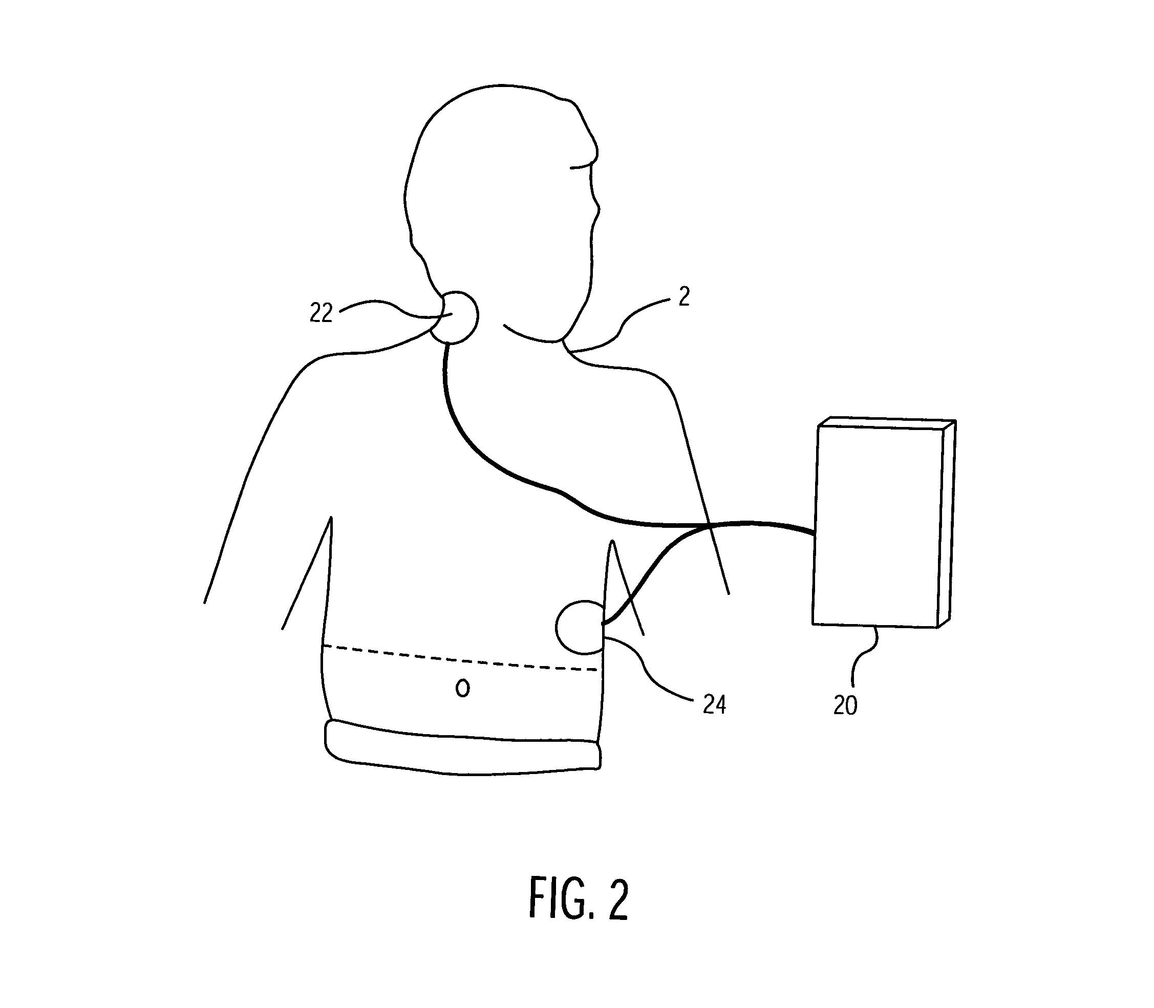
[0024]FIG. 2 illustrates a defibrillator system 20 with a pair of electrodes 22 and 24 according a preferred embodiment of the present invention as it would be applied to a cardiac arrest victim 2. As shown in FIG. 2, one electrode 22 (hereinafter referred to as “necktrode”) is positioned on the right side of the patient's neck 2, above the collarbone, whereas the other electrode 24 is positioned at the lower left base of t...


PUM


Abstract

A defibrillator having a pair of electrodes for delivering an impedance-compensated defibrillation shock and a method thereof is provided. The defibrillator can be deployed rapidly and effectively with no or minimal clothing and hair removal. To achieve this, one electrode is coupled to a neck region of the patient, whereas the other electrode is coupled to the patient's body. Both attachment areas are easily accessible to the rescuer, thus allowing a minimally trained user to easily deploy the defibrillator to treat the patient. A wide range of energy levels that are safe for the patient can be generated selectively based on the patient impedance. The presence of voids in the electrodes decrease the effective shock impedance of the electrodes, thus allowing the defibrillator to operate at a lower level of energy when delivering the electrical pulse to the victim's heart.

Description

BACKGROUND OF THE INFORMATION[0001]1. Field of the Invention[0002]The present invention relates to equipments used in the electrical treatment and monitoring of human bodies. More specifically, the present invention relates to a defibrillator using impedance-compensated defibrillation pulses to apply treatment by contact with the surface of a patient's skin, which is most conveniently accessible to the rescuer.[0003]2. Description of the Related Art[0004]Sudden cardiac arrest is often caused by ventricular fibrillation (VF) in which abnormal and very fast electrical activity occurs in the heart. During VF, the heart cannot pump blood effectively as it causes the individual muscle fibers within the heart to contract in an unsynchronized way. In treating victims of cardiac arrest with a defibrillator, it is important that the treatment be performed very rapidly as their chances of surviving the cardiac arrest decrease drastically over time following the cardiac arrest. Studies have sh...

Claims


Application Information

Patent Timeline
Patent Type & Authority Patents(United States)
IPC IPC(8): A61N1/18A61N1/04A61N1/39
CPCA61N1/3943A61N1/3925A61N1/046
Inventor SNYDER, DAVIDLYSTER, TOMBISHAY, JONBARDY, GUSTMORGAN, CARL
Owner KONINKLIJKE PHILIPS ELECTRONICS NV
Why Eureka
Try Eureka