
Universal mounting arrangement for components of an electronic enclosure

a technology for mounting arrangements and components, applied in the direction of electrical apparatus casings/cabinets/drawers, cable installation in cable chambers, coupling device connections, etc., can solve the problems of time-consuming and difficult, if not impossible, retrofit of bracket systems for technicians in the field

Inactive Publication Date: 2006-05-02
CHARLES INDS
View PDF17 Cites 26 Cited by
  • Summary
  • Abstract
  • Description
  • Claims
  • Application Information

AI Technical Summary

Problems solved by technology

Unfortunately, the existing mounting arrangements for pedestal bracket systems pose a number of problems.
For example, with many mounting arrangements, it can be difficult for a technician to insert and remove the bracket system in the field.
However, such a retrofit can be time consuming and difficult, if not impossible, with existing mounting arrangements.

Method used


Image

  • Universal mounting arrangement for components of an electronic enclosure
  • Universal mounting arrangement for components of an electronic enclosure
  • Universal mounting arrangement for components of an electronic enclosure

Examples


Embodiment Construction

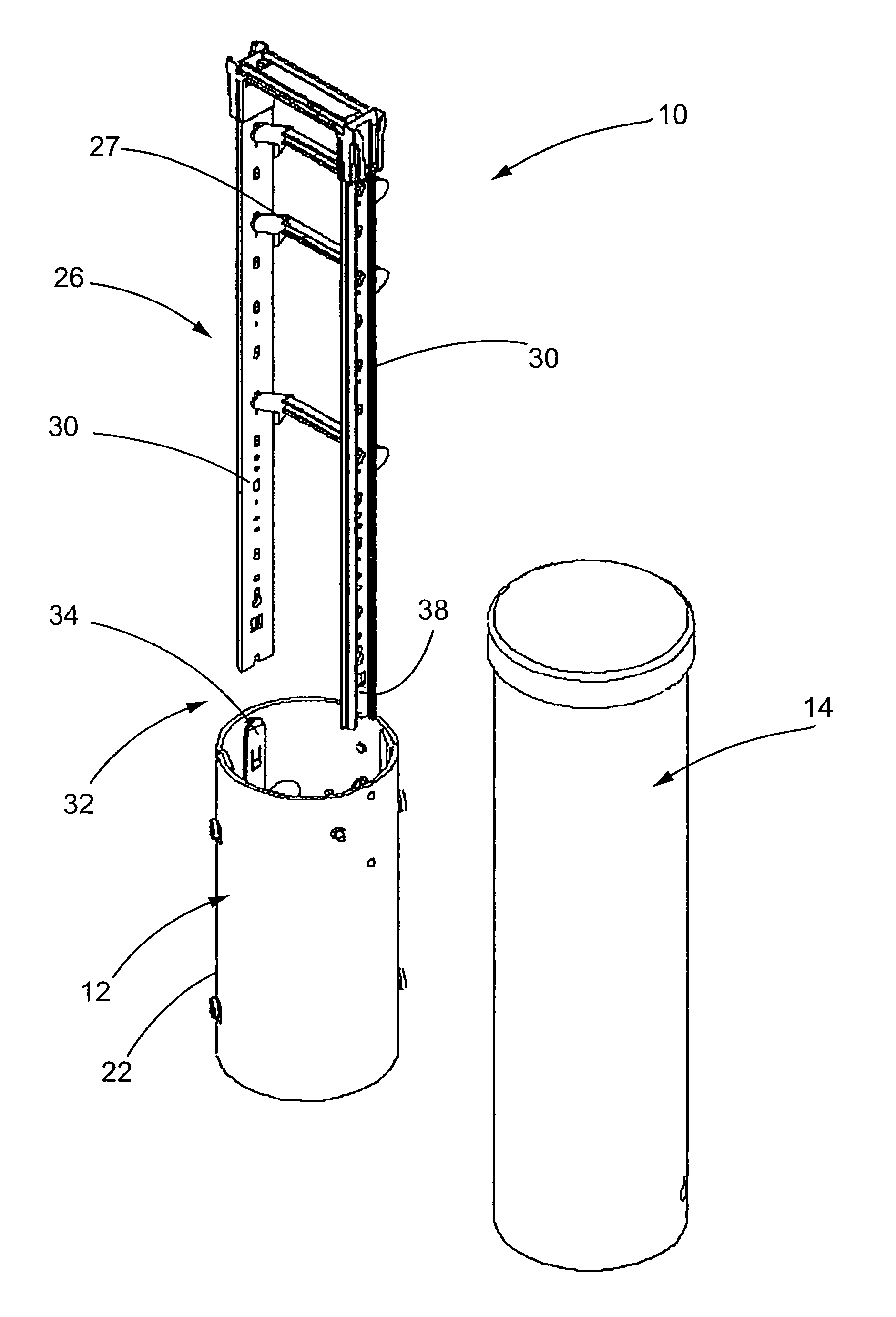
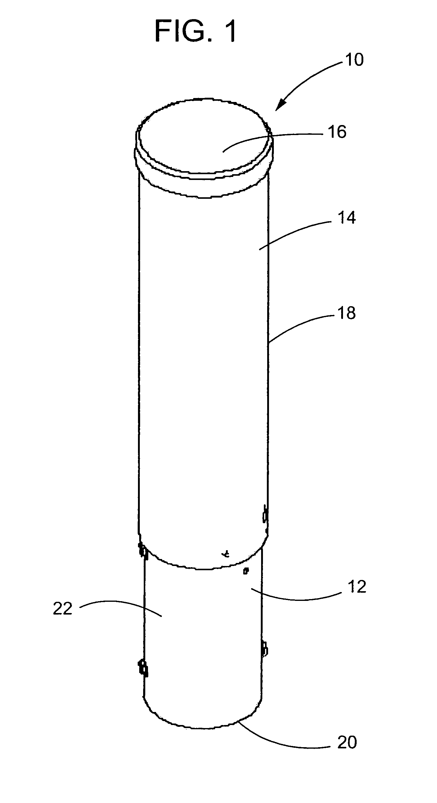
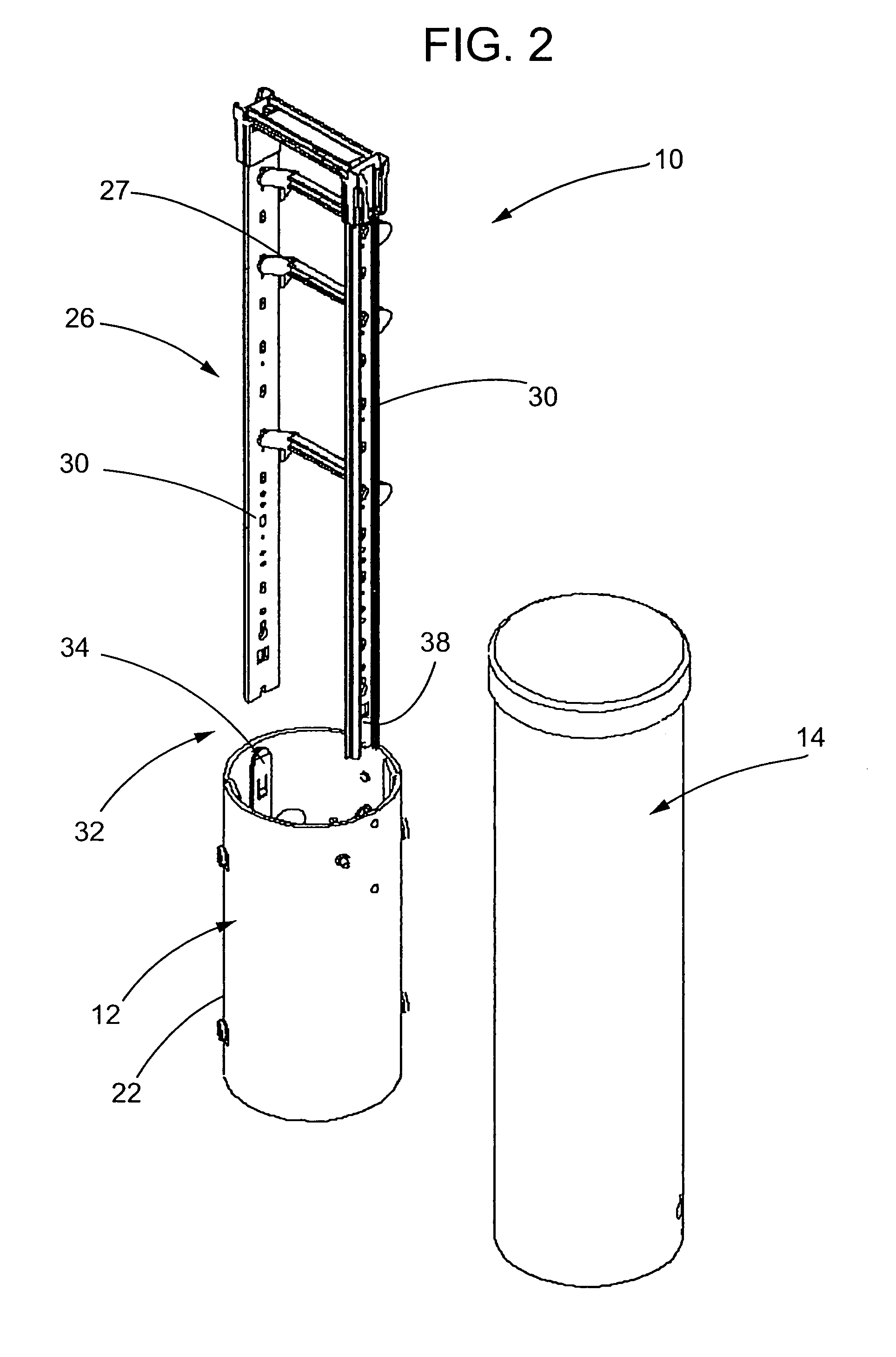
[0014]Referring now to FIGS. 1 and 2 of the drawings, there is illustrated an exemplary pedestal enclosure 10 constructed in accordance with the teachings of the present invention. The illustrated pedestal enclosure 10 includes a base section 12 and a cover or dome 14. The cover 14 nests in a telescoping fashion over the base section 12 so as to define an interior space within the pedestal enclosure 10. This interior space can be used to house electronic equipment such as used in telecommunications, cable television or power transmission applications. The illustrated pedestal enclosure 10 is cylindrical in shape with both the cover 14 and the base section 12 including a respective end wall 16, 20 and a respective sidewall 18, 22. The cover 14 and base section 12 can be secured together by a lock mechanism. As will be appreciated by those skilled in the art, the present invention is not limited to any particular pedestal enclosure size or configuration. Moreover, while the present in...


PUM


Abstract

A pedestal enclosure for electronic components is provided. The pedestal enclosure includes a base section and a cover engageable with the base section so as to define an interior space. The bracket system has at least two side rails. The pedestal enclosure further includes a mounting arrangement for releasably mounting a bracket system to the base section. The mounting arrangement includes a channel section at a lower end of each of the side rails of the bracket system and a mounting part supported on the base section. Each of the mounting parts is configured and arranged to be received in and engage a respective one of the channel sections. The mounting arrangement includes a manually releasable locking mechanism.

Description

FIELD OF THE INVENTION[0001]This invention pertains to electronic enclosures and, more particular, to a universal mounting arrangement for components of an electronics enclosure.BACKGROUND OF THE INVENTION[0002]Pedestal style electronics enclosures are used in telecommunications systems to house splices or terminal connections between service wires or distribution wires and buried telephone cables. Such pedestal enclosures can also be used to house connections to other types of buried utility cables such as for cable television or power distribution. Since pedestal enclosures are located outdoors, they must be substantially weather tight in order to protect the electronic connections from adverse environmental conditions such as wind, rain, snow and flooding. The pedestal enclosures also have to be relatively secure in order to guard against entry by unauthorized personnel and durable in order to withstand the wear-and-tear associated with being located in an outdoor environment.[00...

Claims


Application Information

Patent Timeline
Patent Type & Authority Patents(United States)
IPC IPC(8): H02G3/08H02G9/10H05K7/18
CPCH05K7/186H02G9/10
Inventor HARWOOD, WALTER T.
Owner CHARLES INDS
Learn More