
Bird feeder

a feeder and bird technology, applied in the field of bird feeders, can solve the problems of easy breakage of the swinging selector of the conventional bird feeder, frequent loss of the feeding port by the user,

Inactive Publication Date: 2006-05-09
DAISY MFG
View PDF18 Cites 43 Cited by
  • Summary
  • Abstract
  • Description
  • Claims
  • Application Information

AI Technical Summary

Problems solved by technology

Disadvantages of these conventional bird feeders include frequent loss of the feeding ports by the user.
Another disadvantage is that a swinging selector of a conventional bird feeder can be broken off easily.

Method used


Image

  • Bird feeder
  • Bird feeder
  • Bird feeder

Examples


Embodiment Construction

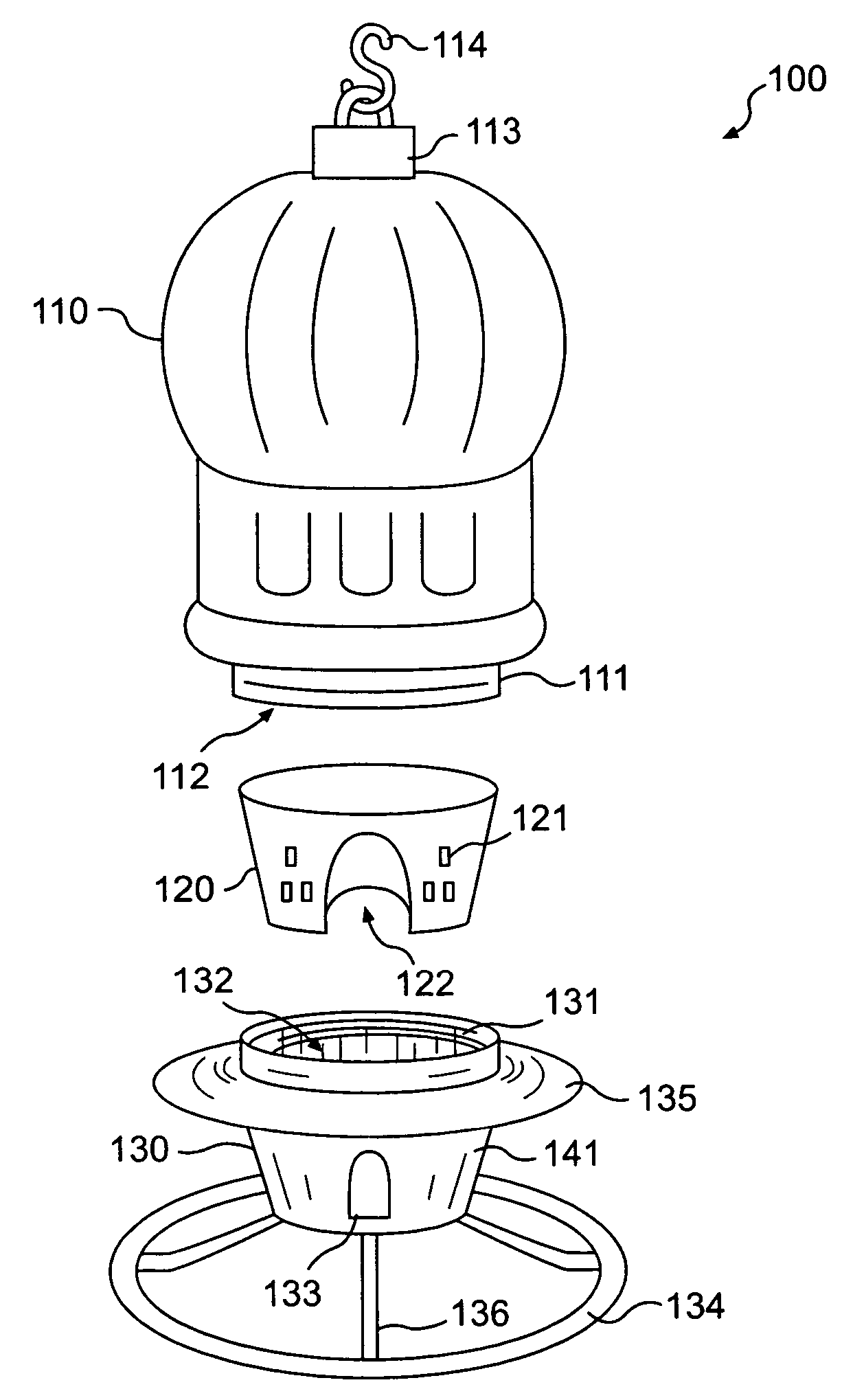
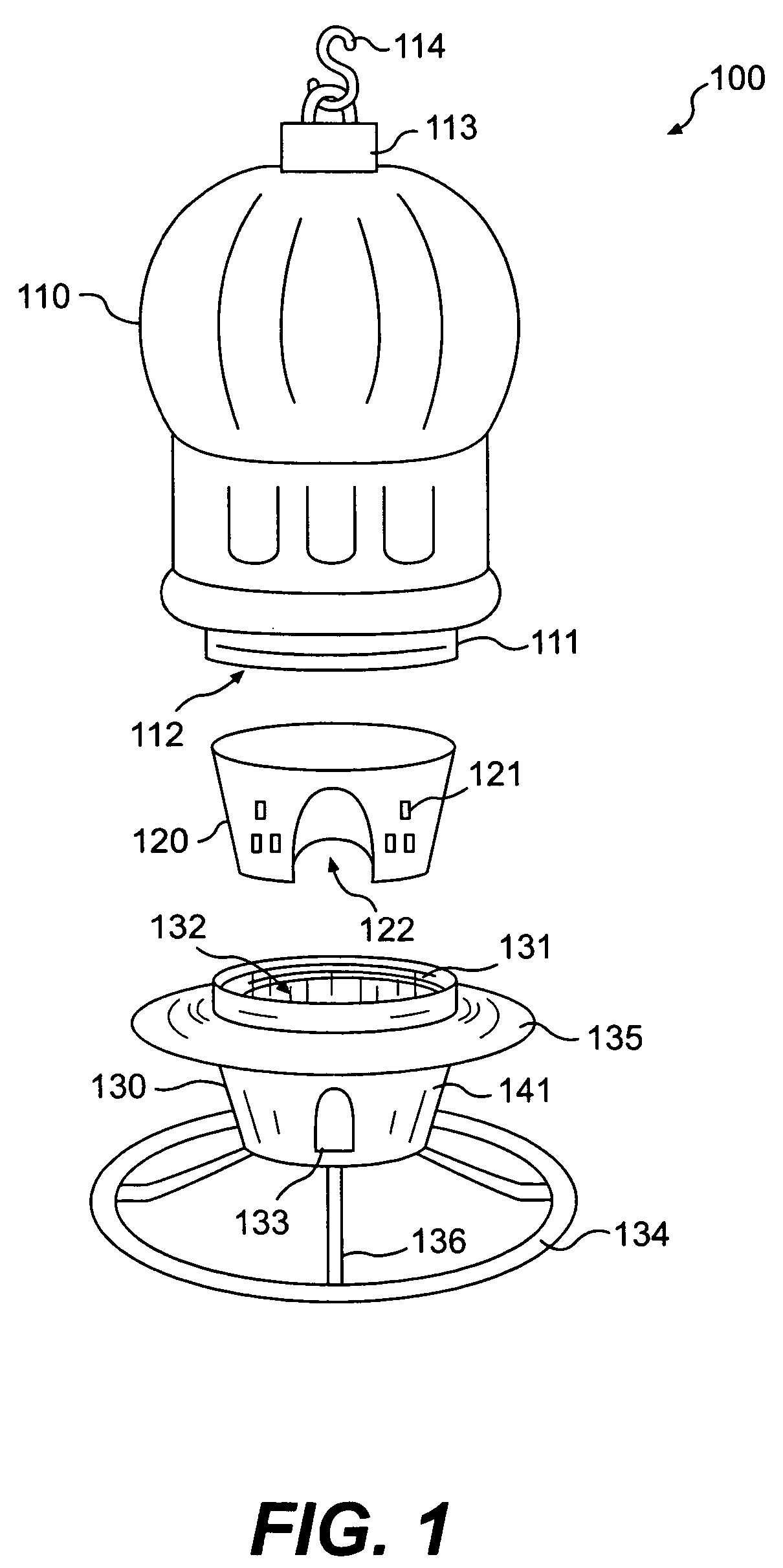
[0008]FIG. 1 is a schematic diagram showing an exploded view of a bird feeder of the invention.

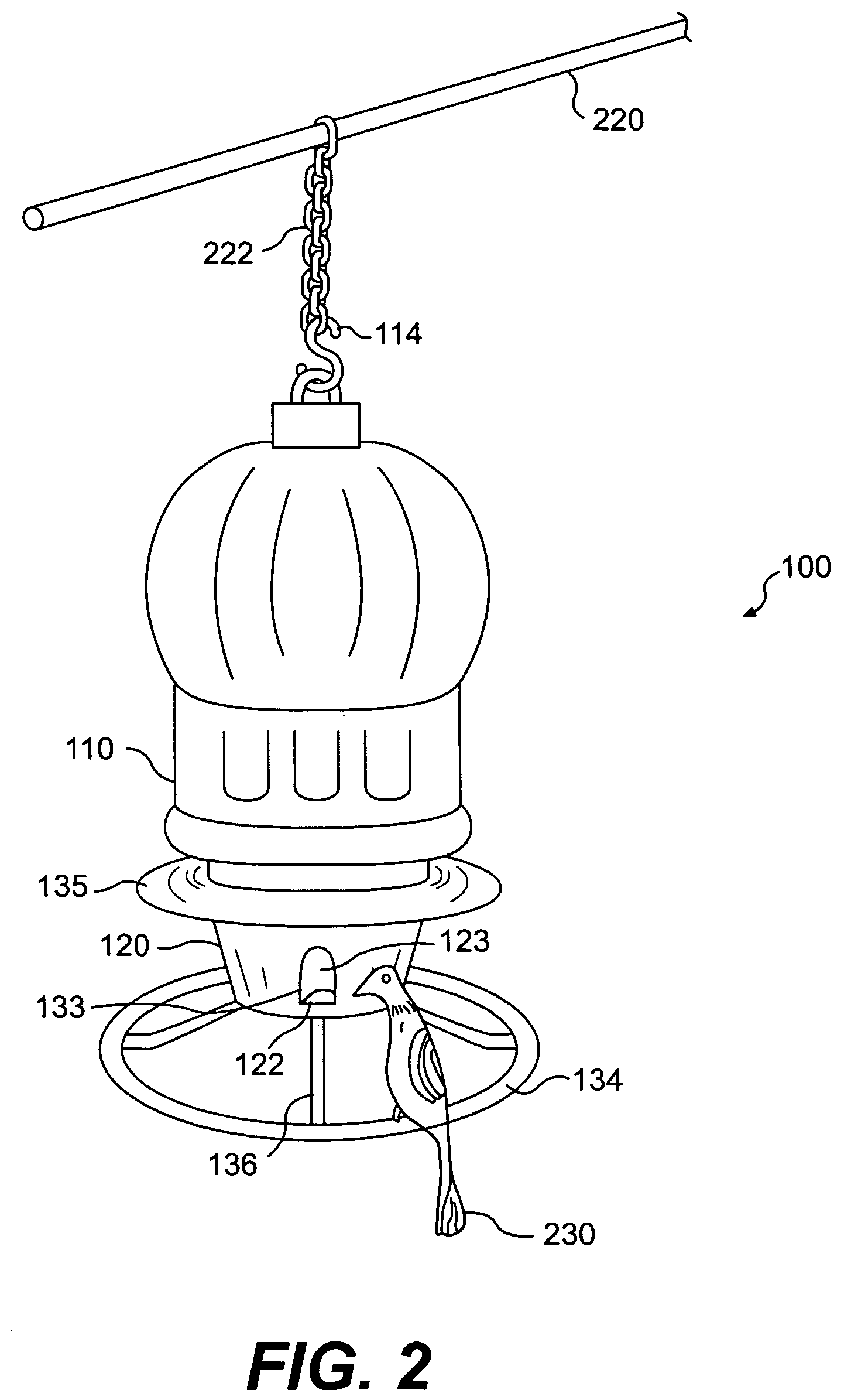
[0009]FIG. 2 is a schematic diagram showing a perspective view of the bird feeder fully assembled.

[0010]FIG. 3 is a schematic diagram showing an exploded view of a container of the bird feeder.

[0011]FIG. 4 is a schematic diagram showing a perspective view of a selector of the bird feeder.

[0012]FIG. 5 is a schematic diagram showing a top view of the selector.

[0013]FIG. 6 is a schematic diagram showing a side view of the selector.

[0014]FIG. 7 is a schematic diagram showing a perspective view of a base of the bird feeder.

[0015]FIG. 8 is a schematic diagram showing a bottom view of the base.

[0016]FIG. 9 is a schematic diagram showing an alternative method for using the bird feeder.

[0017]FIG. 10 is a schematic diagram showing an alternative design of the container.

[0018]FIG. 11 is a schematic diagram showing an alternative design of the base having a dome-shape rain guard with ribs.

[0019]FIG. 1...


PUM


Abstract

A bird feeder having a container, a selector, and a base is disclosed. The selector has at least one large opening and at least one small opening. The base includes at least one feeding port. When one of the openings is aligned with the feeding port, the other opening is covered by a perimeter wall of the base. In preferred embodiments, the base includes a rain guard above the feeding ports.

Description

[0001]This is a continuation application of application Ser. No. 10 / 339,316 filed Jan. 10, 2003 now U.S. Pat. 6,834,616, which is incorporated by reference in its entirety.BACKGROUND[0002]1. Field of the Invention[0003]The present invention relates generally to a bird feeder and, more particularly, to a bird feeder having a food selector.[0004]2. Background of the Invention[0005]Commonly available bird feeders can be used with only one type of seed. For example, some bird feeders are used to store and dispense larger seeds (e.g., sunflower seeds, safflower seeds, or a mixed seeds blend), while other bird feeders are designed for smaller seeds (e.g., thistle seeds, finch seeds, and niger seeds).[0006]Few bird feeders are designed to selectively feed one of larger and smaller seeds. These bird feeders are equipped with feeding ports that are externally removable or a swinging selector. A larger feeding port is attached to these bird feeders to allow larger seed size use. The larger fe...

Claims


Application Information

Patent Timeline
Patent Type & Authority Patents(United States)
IPC IPC(8): A01K39/01A01K39/012
CPCA01K39/012
Inventor FORT, II, W. GRADY
Owner DAISY MFG
Learn More