Stroke limiter for valve pin actuating mechanism

a technology of actuating mechanism and valve pin, which is applied in the field of injection molding apparatus, can solve problems such as wear or failure of the mechanism

Active Publication Date: 2006-05-23
MOLD MASTERS 2007
View PDF36 Cites 13 Cited by
  • Summary
  • Abstract
  • Description
  • Claims
  • Application Information

AI Technical Summary

Problems solved by technology

During use of such mechanisms however, it can occur that the mechanisms wear or fail where the jaws engage the valve pin or the guide element.

Method used


Image

  • Stroke limiter for valve pin actuating mechanism
  • Stroke limiter for valve pin actuating mechanism
  • Stroke limiter for valve pin actuating mechanism

Examples


Embodiment Construction

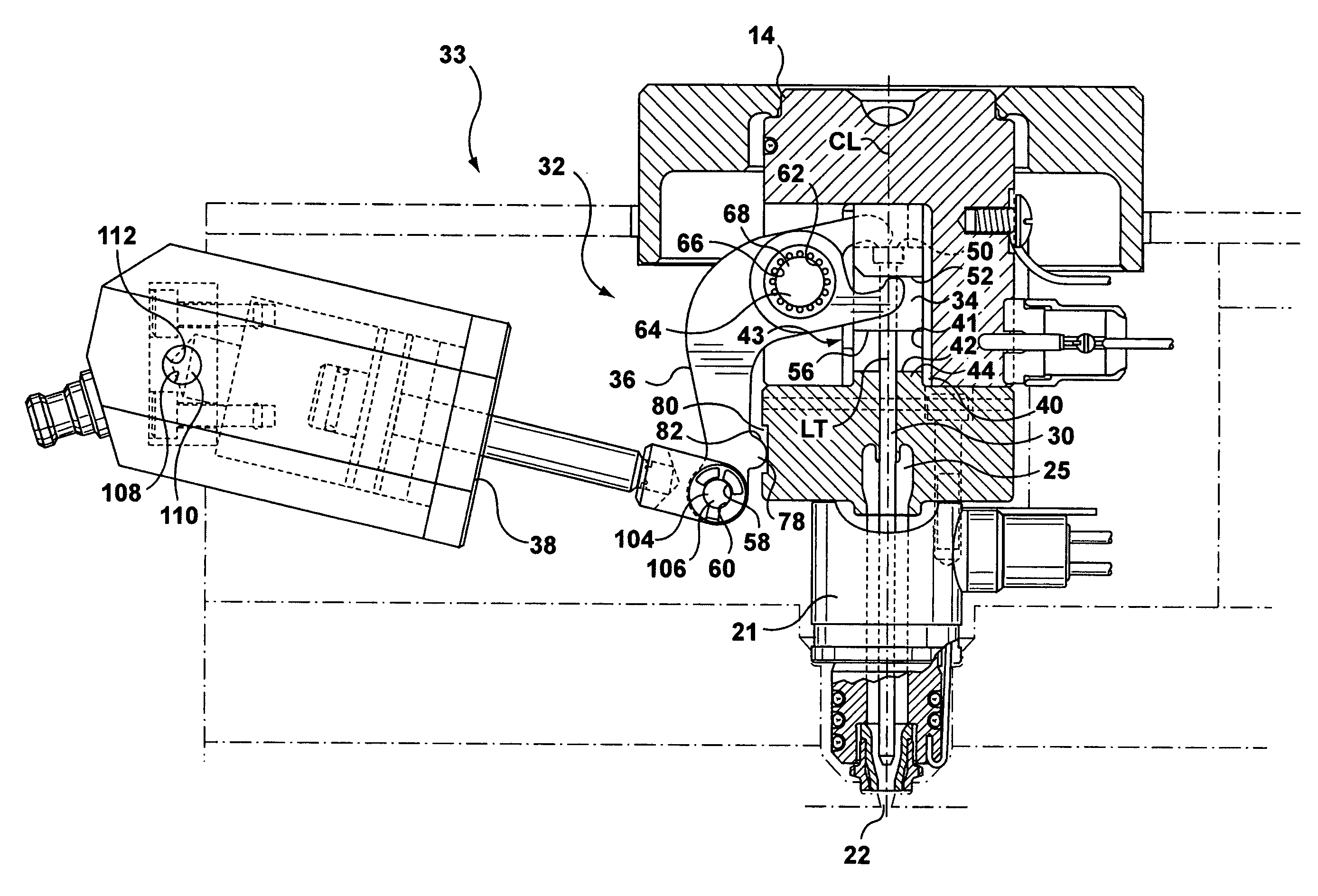
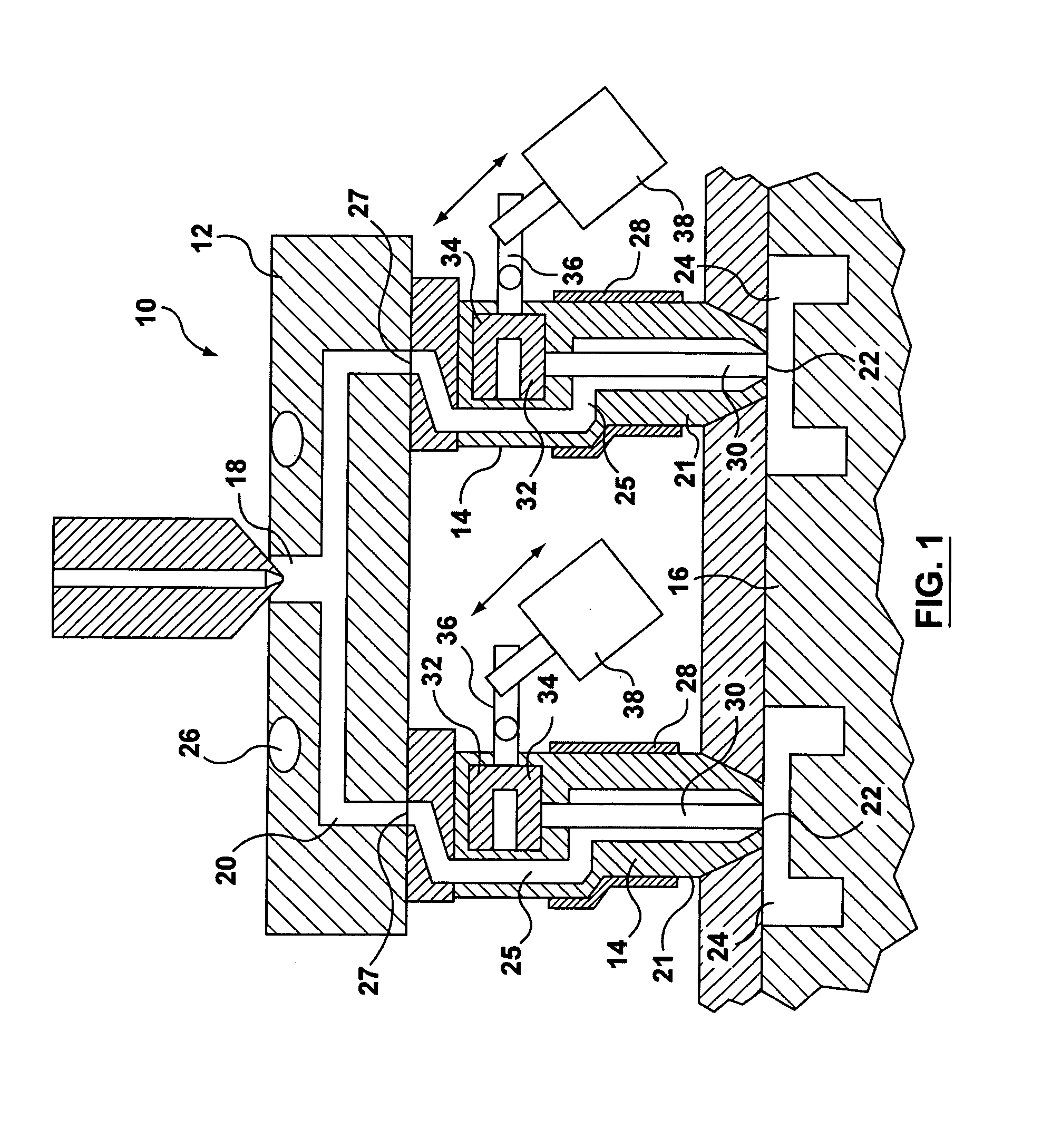
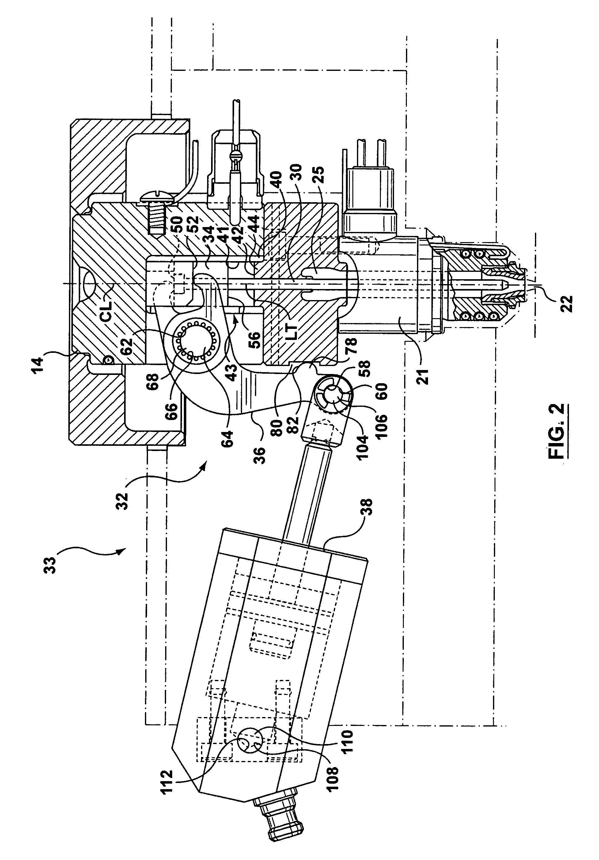
[0018]Reference is made to FIG. 1, which shows an injection molding apparatus in accordance with the present invention, shown generally at 10. As an example embodiment, injection molding apparatus 10 may have a manifold 12, a plurality of nozzles 14, a mold cavity plate 16, a plurality of valve pins 30 and a plurality of valve pin actuating mechanisms 32. Manifold 12 has a mold machine inlet 18, which leads to a plurality of manifold melt passages 20. A heater 26 is included in manifold 12 to heat melt in manifold melt passages 20. Each nozzle 14 includes a nozzle body 21 and a heater 28. Nozzle body 21 defines a nozzle melt passage 25, which has an inlet 27 that is downstream from one of the melt passages 20. Heater 28 is used to heat the flow of melt through nozzle 14. The mold cavity plate 16 defines a plurality of mold cavities 24 that are downstream from the nozzle melt passages 25. The junction between a nozzle melt passage 25 and a mold cavity 24 is referred to as a gate 22. ...


PUM

PropertyMeasurementUnit
angle of rotationaaaaaaaaaa
distanceaaaaaaaaaa
melt flowaaaaaaaaaa

Abstract

A valve pin actuating mechanism for an injection molding apparatus is provided. The injection molding apparatus includes at least one melt channel and a valve pin that is movable in the melt channel. The valve pin actuating mechanism includes an actuator, a linkage element and a stop. The linkage element has a mechanically upstream connector and a mechanically downstream connector. The linkage element is connected at least indirectly to the actuator at the mechanically upstream connector and is connected at least indirectly to the valve pin at the mechanically downstream connector. The linkage element is rotatable by actuation of the actuator. The stop is configured to engage a limit surface to limit the angle of rotation of the linkage element. The stop and the limit surface are configured to engage mechanically upstream from the downstream connector of the linkage element.

Description

FIELD OF THE INVENTION[0001]The invention relates to an injection molding apparatus, and more particularly to a laterally actuated valve pin gating mechanism for an injection molding apparatus.BACKGROUND OF THE INVENTION[0002]In many injection molding apparatuses, a valve pin is used to open and close a gate into a mold cavity in order to control the melt flow into the mold cavity. Depending on the layout constraints in the injection molding apparatus, it can be desirable to provide an actuating mechanism for the valve pin, that extends laterally to the valve pin.[0003]The technical literature shows several hot runner injection nozzle designs having a valve pin actuating mechanism incorporating a rocker arm or a linkage that extends laterally either to engage the valve pin directly, or to engage a guide element, which retains the valve pin. In some configurations the rocker arm engages the valve pin or the guide element opposing jaws, (eg. upper and lower jaws) that capture the valv...

Claims


Application Information

Patent Timeline
Patent Type & Authority Patents(United States)
IPC IPC(8): B29C45/23B29C45/28
CPCB29C45/281B29C2045/2834
Inventor TABASSI, PAYMAN AKHAVAN
Owner MOLD MASTERS 2007
Why Eureka
Try Eureka