Battery charger with improved terminal protection

a battery pack charger and terminal protection technology, applied in the direction of electric vehicles, secondary cell servicing/maintenance, transportation and packaging, etc., can solve the problems of terminal breakage, reduce the utility of the device, suffer damage, etc., and achieve the effect of high waterproofing and dustproofing and maintaining the relatively small size of the charger

Active Publication Date: 2006-06-20
MAKITA CORP
View PDF7 Cites 40 Cited by
  • Summary
  • Abstract
  • Description
  • Claims
  • Application Information

AI Technical Summary

Benefits of technology

[0009]In view of the above-identified problems, an important object of the present invention is to provide a charger that protects the terminals from damage and ensures high waterproofing and dustproofing for the terminals while maintaining the relatively small size of the charger.

Problems solved by technology

While this type of battery charger achieves its intended objective, it is not free from certain problems and inconveniences, thus leaving room for improvement.
For example, as the terminals of a charger of this type are exposed at the connecting portion to the external environment when the battery pack is not attached to the charger, the terminals may break or otherwise suffer damage that may result, for example, from the charger dropping to the floor or, conversely, by an object falling onto the charger.
While this improved arrangement achieves its intended objective, it still suffers from certain deficiencies that reduce the utility of the device.
Depending on the working environment, such as in outdoor environments, this arrangement is susceptible to ingression of rain, dust, and other foreign matter through the through-hole, thereby causing short-circuiting or other such failures.
Another disadvantage associated with the foregoing device is the need to allocate or reserve the space within the housing to allow the terminal cover to be retracted inside the charger.
This results in otherwise unnecessary increases in the size of the entire device.

Method used


Image

  • Battery charger with improved terminal protection
  • Battery charger with improved terminal protection
  • Battery charger with improved terminal protection

Examples


Embodiment Construction

[0032]A preferred embodiment of the present invention will be described hereinafter with reference to the attached drawings.

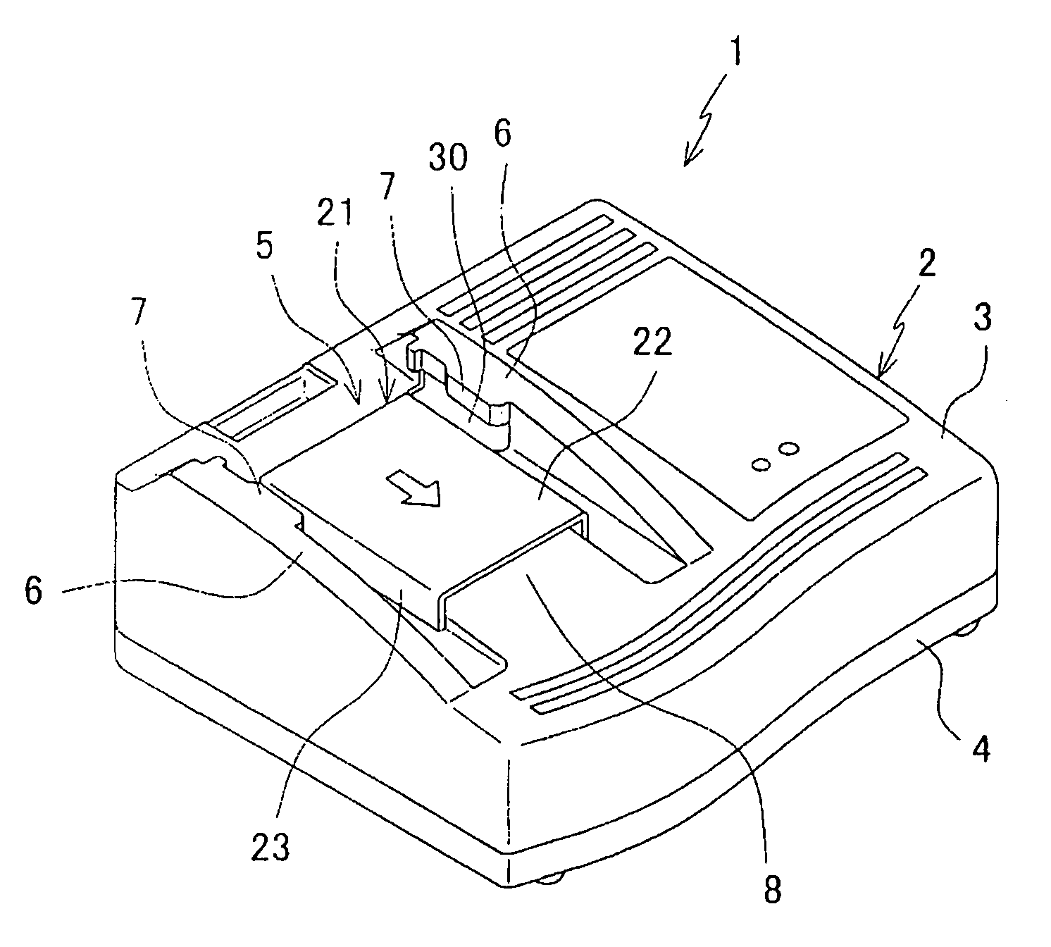
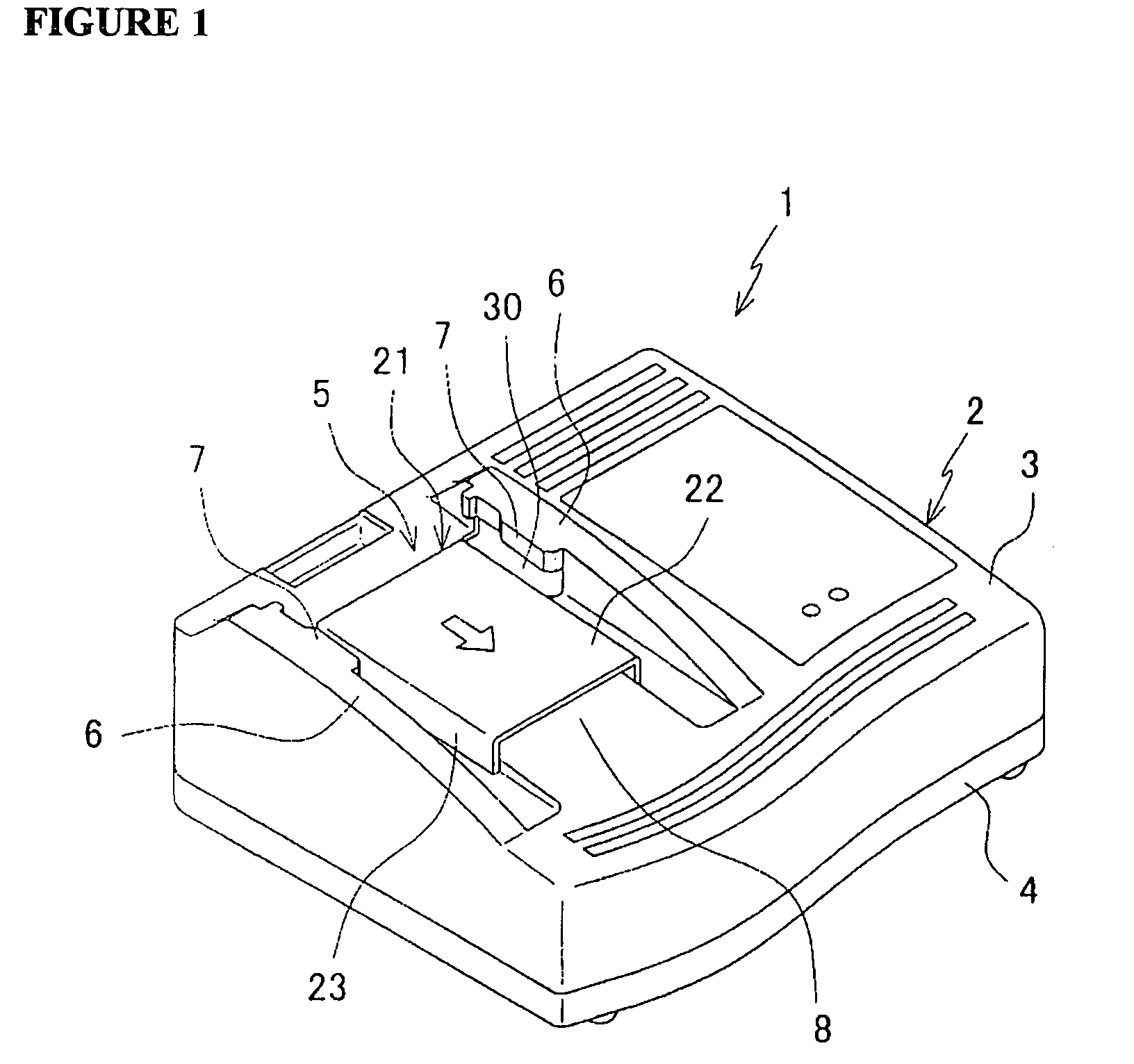
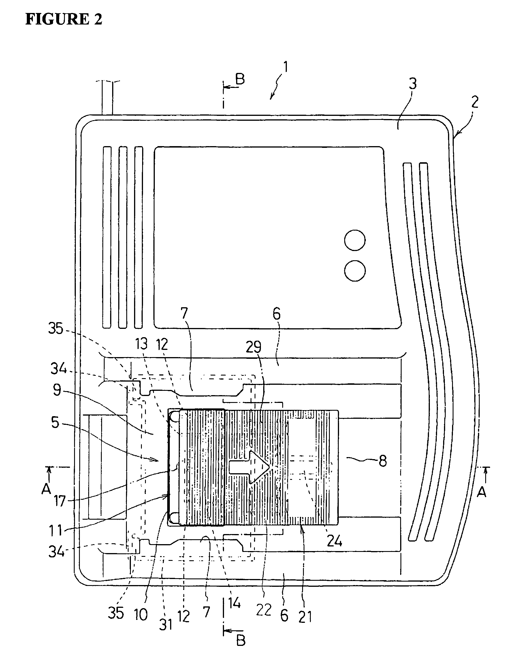
[0033]FIG. 1 is a perspective view of a battery charger 1 in accordance with the present invention; FIG. 2 is a plan view of the charger 1; and FIG. 3 is a cross-sectional view of the charger 1 taken along line A—A of FIG. 2. The charger 1 includes an upper case 3 and a base plate 4 fitted together to form a box enclosure 2 encasing a circuit board for charging (not shown). A connecting portion 5 is provided on the enclosure's upper surface to which a battery pack 40 is attached as shown in FIGS. 7 and 8. The battery pack 40 includes an outer case 41 which contains a plurality of cells. Provided on the top surface of the outer case 41 are a connection block 42 and a pair of parallel slide rails 43 extending in a forward direction (in the direction opposite to the end of the pack's top surface where the connection block 42 is located) on both sides of the connec...


PUM

PropertyMeasurementUnit
sizeaaaaaaaaaa
linear movementaaaaaaaaaa
durabilityaaaaaaaaaa

Abstract

A charger (1) includes a connecting portion (5) provided in an upper case (3) of the charger. The connection portion (5) includes a pair of guide rails (6) to which a battery pack (40) is slidably attached. The charger further includes between the guide rails (6) a terminal block having various terminals (12–14) as well as a slide cover (21) linearly slidable in parallel with the direction in which the battery pack slides on the charger. Under normal operating conditions, the slide cover (21) is biased to a rear position in which the cover (21) is located over and protects a terminal block (11). When the battery pack (40) is set on the charger, the battery pack abuts and slides the slide cover to a forward position in which the terminal block (11) is exposed.

Description

RELATED APPLICATION[0001]This application claims priority on Japanese Patent Application No. 2002-306123 filed on Oct. 21, 2002.BACKGROUND OF THE INVENTION[0002]1. Field of the Invention[0003]The present invention relates to chargers for use with battery packs which are used to run electric power tools. More particularly, the present invention relates to a battery pack charger with an improved mechanism for protecting its terminals.[0004]2. Description of the Related Art[0005]One type of known battery charger includes a connecting portion, such as a pair of guide rails protruding therefrom on which a battery pack is set for charging. A battery pack to be charged by such a charger typically includes a pair of slide rails provided on the surface of the battery pack that is set on the charger during a charge. The slide rails can be engaged with and slid along the guide rails of the charger in order to removably set the pack in place on the charger. When the battery pack is attached to ...

Claims


Application Information

Patent Timeline
Patent Type & Authority Patents(United States)
IPC IPC(8): H02J7/00H01M10/44
CPCH02J7/0045
Inventor ITO, KATSUYASU
Owner MAKITA CORP
Why Eureka
Try Eureka