
Power hand tool foot assembly

a technology of foot assembly and hand tools, which is applied in the field of foot assembly, can solve the problems of time and effort required for tightening and loosening the locking member, the mechanism of locking the foot at a desired angle to the tool housing, and the problem of not being able to meet the needs of use,

Inactive Publication Date: 2006-06-27
NANJING CHERVON IND
View PDF14 Cites 27 Cited by
  • Summary
  • Abstract
  • Description
  • Claims
  • Application Information

AI Technical Summary

Benefits of technology

The present invention is about a power tool foot assembly that can be adjusted to different levels and can lock in place. It includes a platform and a swivel lock that can be locked in place using a lever. Additionally, there is a level adjustable power tool foot assembly that can be attached to a housing and has a blade engaging roller that can be moved into engagement with a blade. The technical effects of this invention are that it allows for easier and more precise use of power tools, especially in situations where the surface being worked on is not perfectly level.

Problems solved by technology

Although tiltable power tool feet are generally known, problems with them remain.
For example, mechanisms for locking the foot at a desired angle to the tool housing are often burdensome to use.
Tightening and loosening of the locking member requires time and effort.
To date, however, the locking levers used have been relatively costly to manufacture and cumbersome to install and adjust.
Further, known hand operating levers may offer less frictional holding strength than do tool tightened threaded bolts and the like.
The substantial vibration developed during operation of a jigsaw can result in the foot slipping and changing orientation angle when locked with known levers.
Such configurations have met only limited success, however.
Vibration of the tool may result in the locking formation disengaging from the notch.
Vibration may also cause the foot to disengage from the stud when it separates vertically from the tool over the top of the stud.
These and other problems remain unresolved in the art.

Method used


Image

  • Power hand tool foot assembly
  • Power hand tool foot assembly
  • Power hand tool foot assembly

Examples


Embodiment Construction

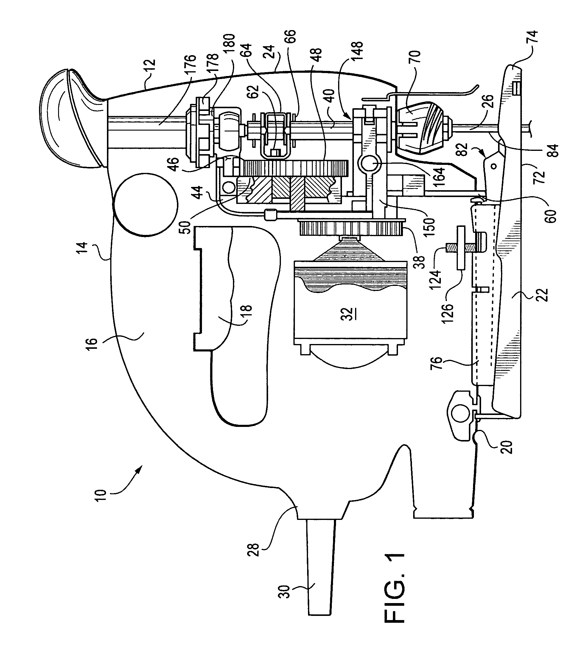
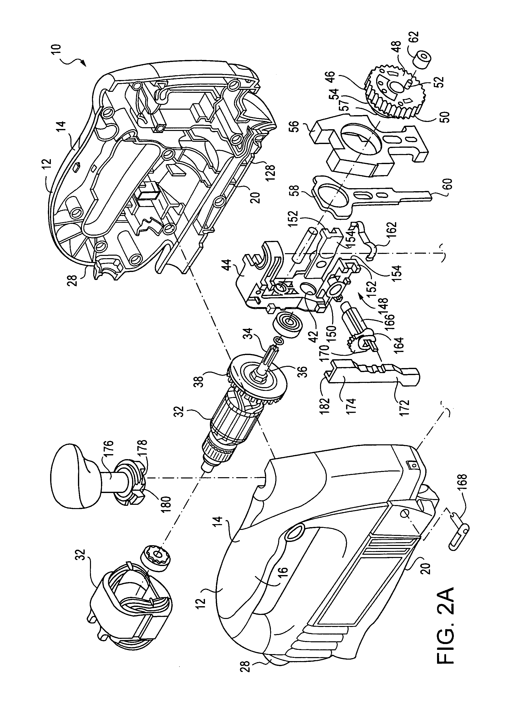
[0019]Turning now to the drawings, FIG. 1 shows a jigsaw generally at 10 that includes a housing 12. A motor such as an AC, a DC, or a universal motor is contained in the housing 12, and is linked to a reciprocating saw blade 14. An on / off switch 16 controls the motor. Power is supplied to the motor using the cord 17, while a battery or other portable source maybe used to power a DC or universal motor. Those knowledgeable in the art will appreciate that these components of jigsaws are generally known, and accordingly need not be discussed in detail herein. The preferred jigsaw 10 also includes a scroll controller 18 for turning the blade 14 relative to the housing 12 to perform scroll cutting.

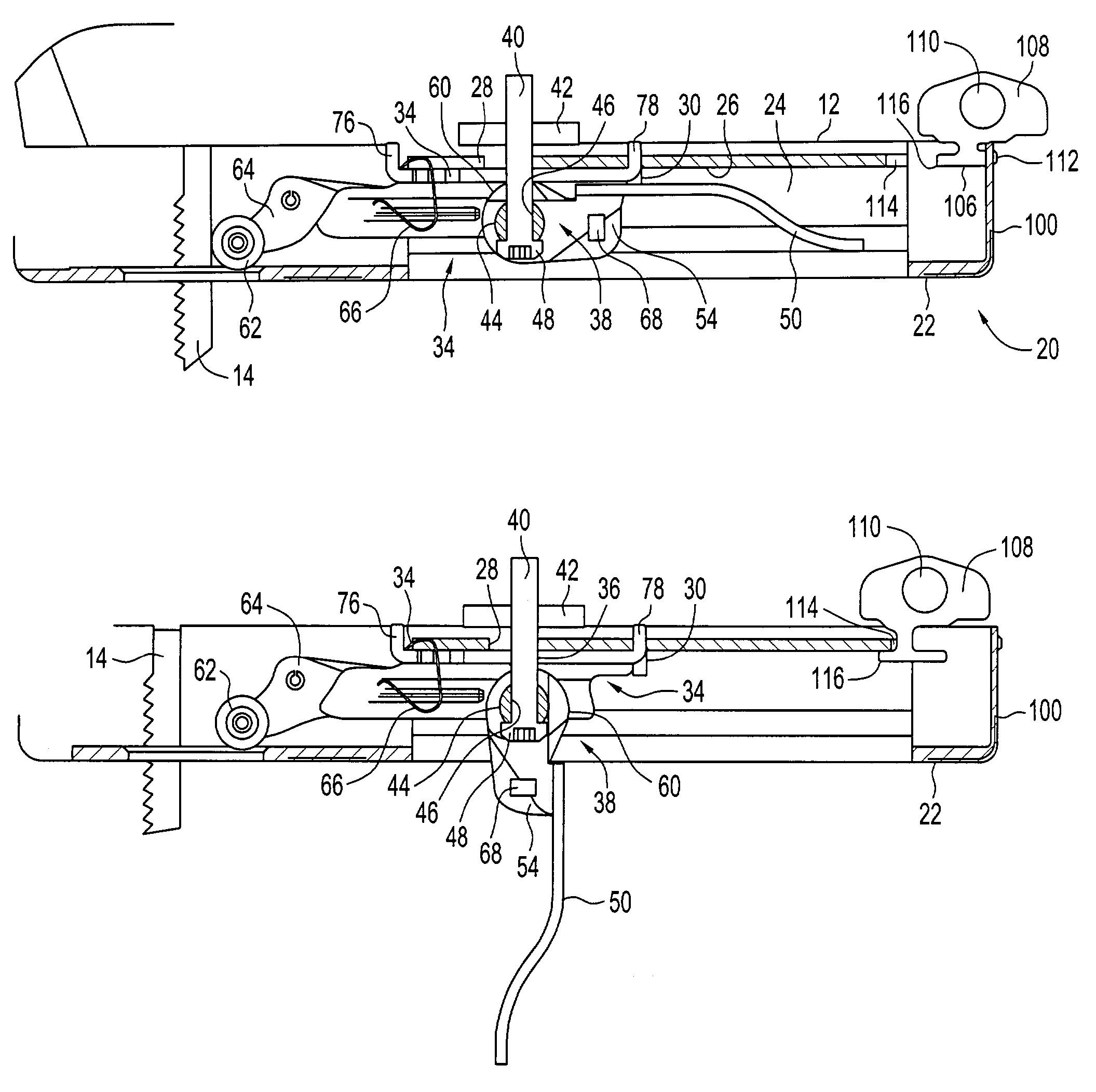
[0020]The jigsaw 10 also has a foot assembly shown generally at 20 that includes a platform 22 that lies along a generally flat plane for traveling over a workpiece. As shown by FIGS. 2, 5, 6 and 7, a generally curved arch portion 24 rises from the platform 22. The arch portion 24 has a T-shape...


PUM

PropertyMeasurementUnit
angleaaaaaaaaaa
angleaaaaaaaaaa
widthaaaaaaaaaa

Abstract

A power hand tool foot assembly includes a platform having an arch portion. A swivel lock is within the arch portion, with a mount connecting the swivel lock to the tool housing. A lever is pivotally mounted on the mount. When the lever is in a locked position, the swivel lock and platform are locked in place. When the lever is in an open position, the longitudinal and angular position of the platform and swivel lock may be adjusted.

Description

FIELD OF THE INVENTION[0001]The present invention is related to power hand tools, as well as to foot assemblies for such power hand tools.BACKGROUND OF THE INVENTION[0002]Electric power hand tools such as portable electric jigsaws and the like are known in the art. Generally, they include an electric motor for driving a shaft, with a tool such as a saw blade attached to the shaft. The electric motor is often an AC, DC or a universal motor, and is contained in a housing. In the case of a jigsaw as well as other cutting tools, a so-called foot may be provided connected to the base of the tool housing that includes a generally flat platform for engaging a workpiece surface. The foot allows the power tool to move over the workpiece surface to achieve an accurate and desired result.[0003]Some jigsaws and other power tools may feature a foot assembly that has a foot that is tiltably connected to the tool housing. By tilting the foot, the tool blade is able to address a workpiece at an ang...

Claims


Application Information

Patent Timeline
Patent Type & Authority Patents(United States)
IPC IPC(8): B23D49/10B23D49/16
CPCB23D49/167Y10T83/6875
Inventor TAM, RAMONMORENO, JAIMEWEILAND, CHRISTOPHERECKERT, LEEPELISEK, ROBERT
Owner NANJING CHERVON IND
Learn More