Universal wall mounting bracket

a universal, wall mounting technology, applied in the direction of washstands, scaffold accessories, light support devices, etc., can solve the problems of reducing the available workspace occupied by equipment, inability to place equipment in a desired location, eye strain, neck strain,

Active Publication Date: 2006-06-27
HUMAN ACTIVE TECH LLC
View PDF43 Cites 75 Cited by
  • Summary
  • Abstract
  • Description
  • Claims
  • Application Information

AI Technical Summary

Problems solved by technology

One drawback to these configurations is the reduction in available workspace taken up by the equipment.
Another drawback is the inability to place the equipment in a desired location.
A further drawback is the potential for eye strain, neck strain and / or a cumulative trauma disorder such as carpel tunnel syndrome from non-ergonomic placement of devices such as monitors and keyboards.
While this may free up workspace, it often places the equipment in an undesirable location.
However, in many cases it is not desirable to tie the extension arm to the workspace itself.
A drawback to mounting equipment to a slat wall in this manner is that there are numerous slat wall configurations produced by different manufacturers.
Another drawback in mounting equipment to a slat wall is placement of cables associated with the equipment.
The cables may hang loose, providing a cumbersome and inelegant solution.

Method used


Image

  • Universal wall mounting bracket
  • Universal wall mounting bracket
  • Universal wall mounting bracket

Examples


Embodiment Construction

[0030]The aspects, features and advantages of the present invention will be appreciated when considered with reference to the following description of preferred embodiments and accompanying figures. In describing the preferred embodiments of the invention illustrated in the figures, specific terminology will be used for the sake of clarity. However, the invention is not intended to be limited to the specific terms so selected, and it is to be understood that each term selected includes all technical equivalents that operate in a similar manner to accomplish a similar purpose.

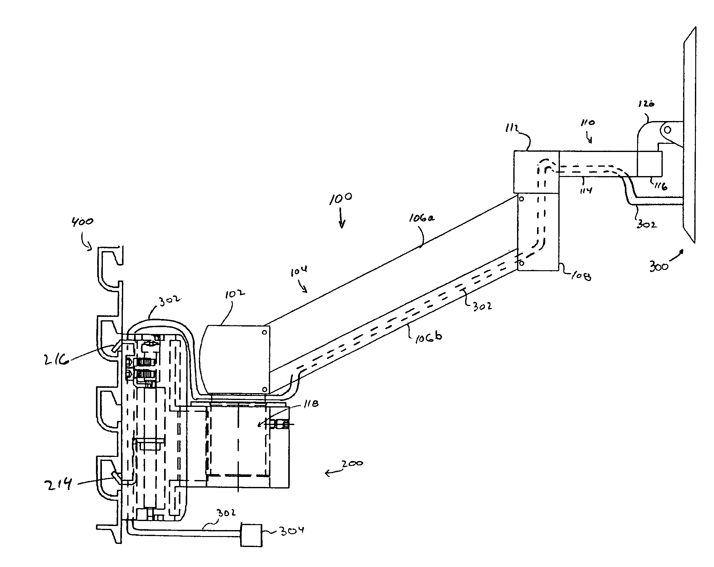
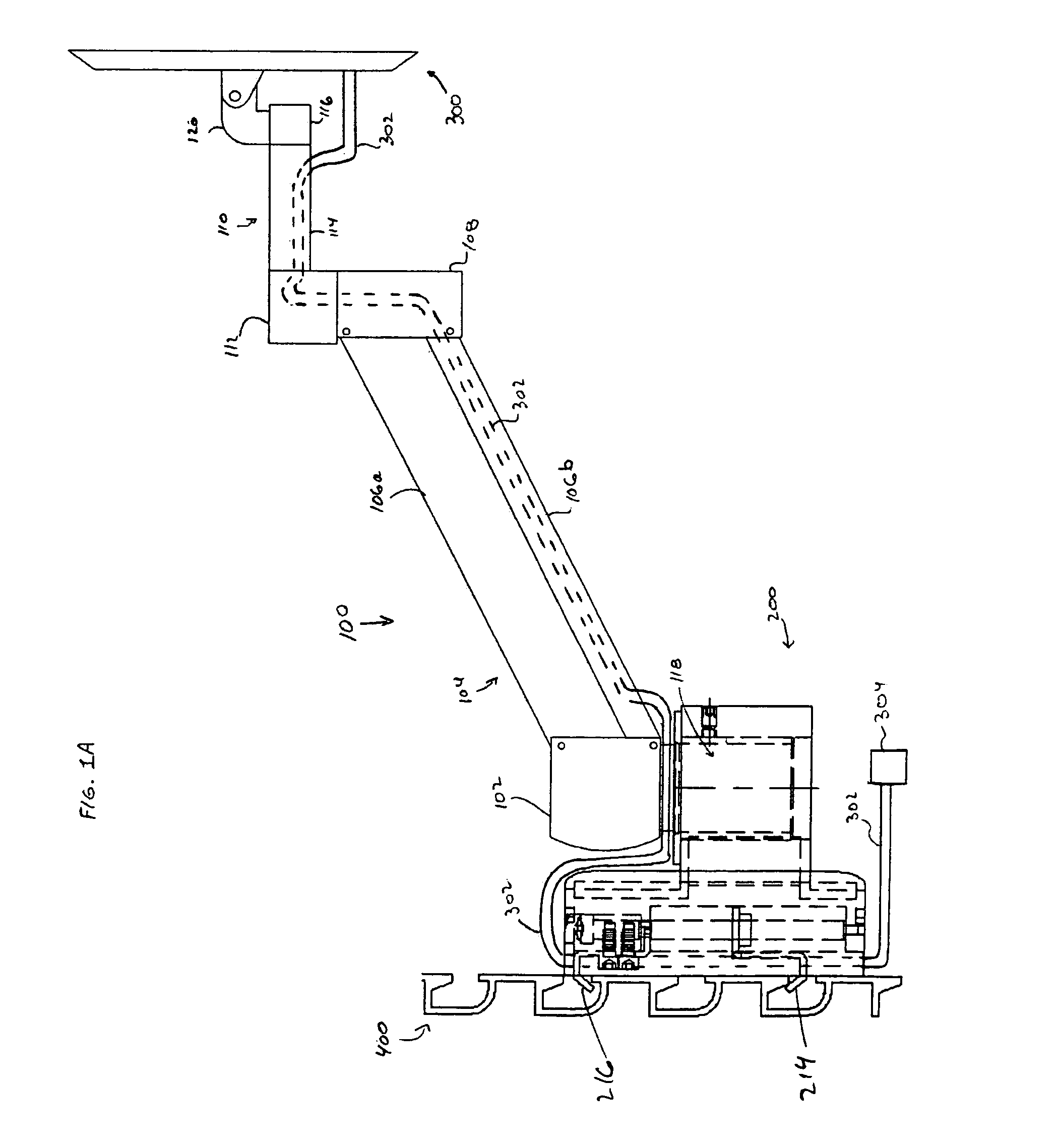
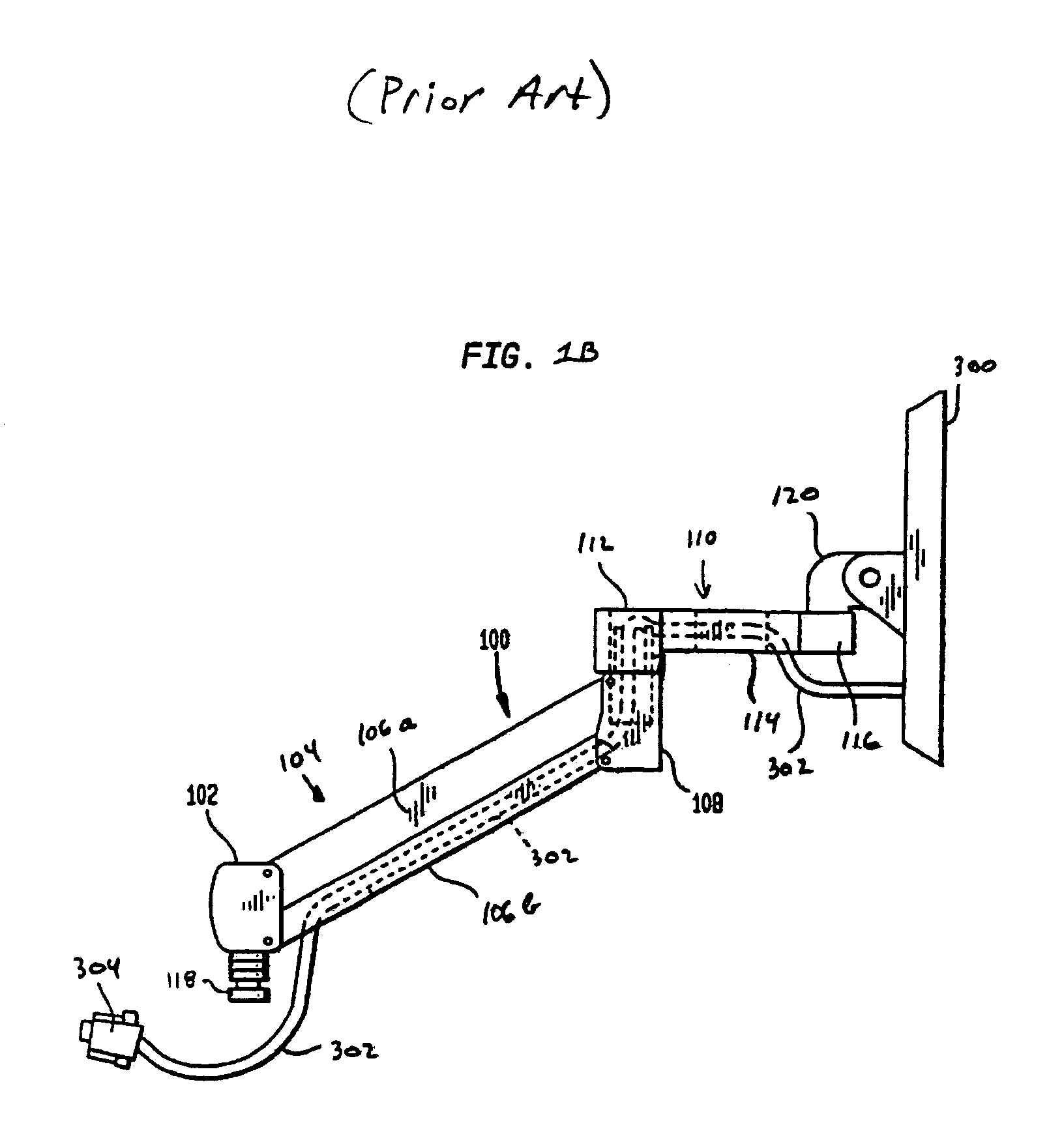
[0031]FIG. 1A illustrates an extension arm 100 engaged at one end to a mounting assembly 200 and attached to an electronic device 300 such as a flat panel monitor at the other end. While the electronic device 300 is described below as a flat panel monitor or other video monitor, the invention is not limited to use with such devices, and may be used with a wide variety of equipment. A cable 302 is connected to th...


PUM


Abstract

A wall mount assembly is provided for attaching an electronic device to a slat wall. The wall mount assembly includes a main body, a mount and a pair of clip assemblies to connect to the slat wall. The mount has a central opening to receive a support arm that holds the electronic device. The clip assemblies may be spaced apart on arms attached to the main body. The arms and main body are dimensioned so that electrical cables connected to the electronic device can be passed between the main body and the slat wall, providing cable management. Furthermore, a wall mount assembly kit may include assorted clips or brackets for attaching to different slat wall configurations.

Description

BACKGROUND OF THE INVENTION[0001]The present invention relates to a bracket for positioning devices. More particularly, the present invention relates to a universal wall-mounting assembly attachable to different slat wall configurations.[0002]In the past people have placed video monitors and other electronic equipment on desks, tabletops, or upon other equipment such as personal computers or workstations. One drawback to these configurations is the reduction in available workspace taken up by the equipment. Another drawback is the inability to place the equipment in a desired location. A further drawback is the potential for eye strain, neck strain and / or a cumulative trauma disorder such as carpel tunnel syndrome from non-ergonomic placement of devices such as monitors and keyboards.[0003]Different products have been provided in order to overcome these obstacles. For example, in one solution, a monitor stand or printer stand elevates the apparatus over other equipment on a desk. Wh...

Claims


Application Information

Patent Timeline
Patent Type & Authority Patents(United States)
IPC IPC(8): E04G3/00F16B2/12F16M11/04F16M13/02
CPCF16M11/04F16M11/10F16M11/2014F16M13/02F16M11/24F16B2/12Y10S248/917F16M2200/065F16M2200/068
Inventor ODDSEN, JR., ODD N.DERRY, BRADLEY A.
Owner HUMAN ACTIVE TECH LLC
Why Eureka
Try Eureka