Integrated pointer hub and warning indicator

a pointer hub and warning indicator technology, applied in the field of integrated pointer hubs, can solve the problems of limiting the ability to use multiple pointers, requiring a single or upright orientation of indicators, and requiring a turn signal, etc., to achieve efficient backlighting multiple informational displays and efficient use of spa

Inactive Publication Date: 2006-06-27
YAZAKI NORTH AMERICA
View PDF5 Cites 59 Cited by
  • Summary
  • Abstract
  • Description
  • Claims
  • Application Information

AI Technical Summary

Benefits of technology

[0008]A further object of the invention is to efficiently backlight multiple informational displays on a single instrument panel gauge.

Problems solved by technology

But the use of such reflectors does not appear to have been significantly expanded within the art to provide efficient use of backlighting for different types of displays on a single dial or gauge face.
This would make any indicator requiring a single or upright orientation, such as a turn signal, impractical.
In addition, since the cap member is attached to the pointer drive shaft, it can only act as a hub for a single pointer, severely limiting the ability to use multiple pointers, and therefore a plurality of information displays, on a single dial face.

Method used


Image

  • Integrated pointer hub and warning indicator
  • Integrated pointer hub and warning indicator
  • Integrated pointer hub and warning indicator

Examples


Embodiment Construction

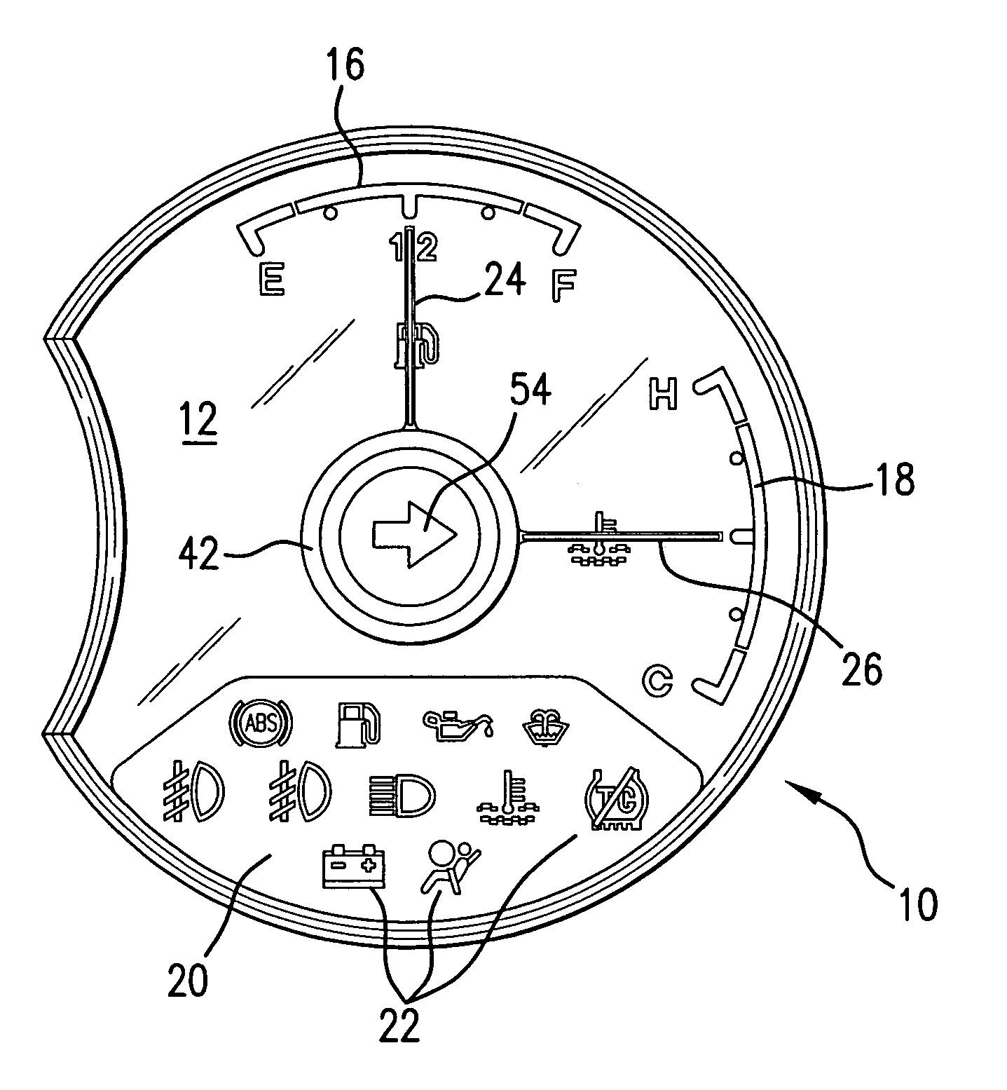
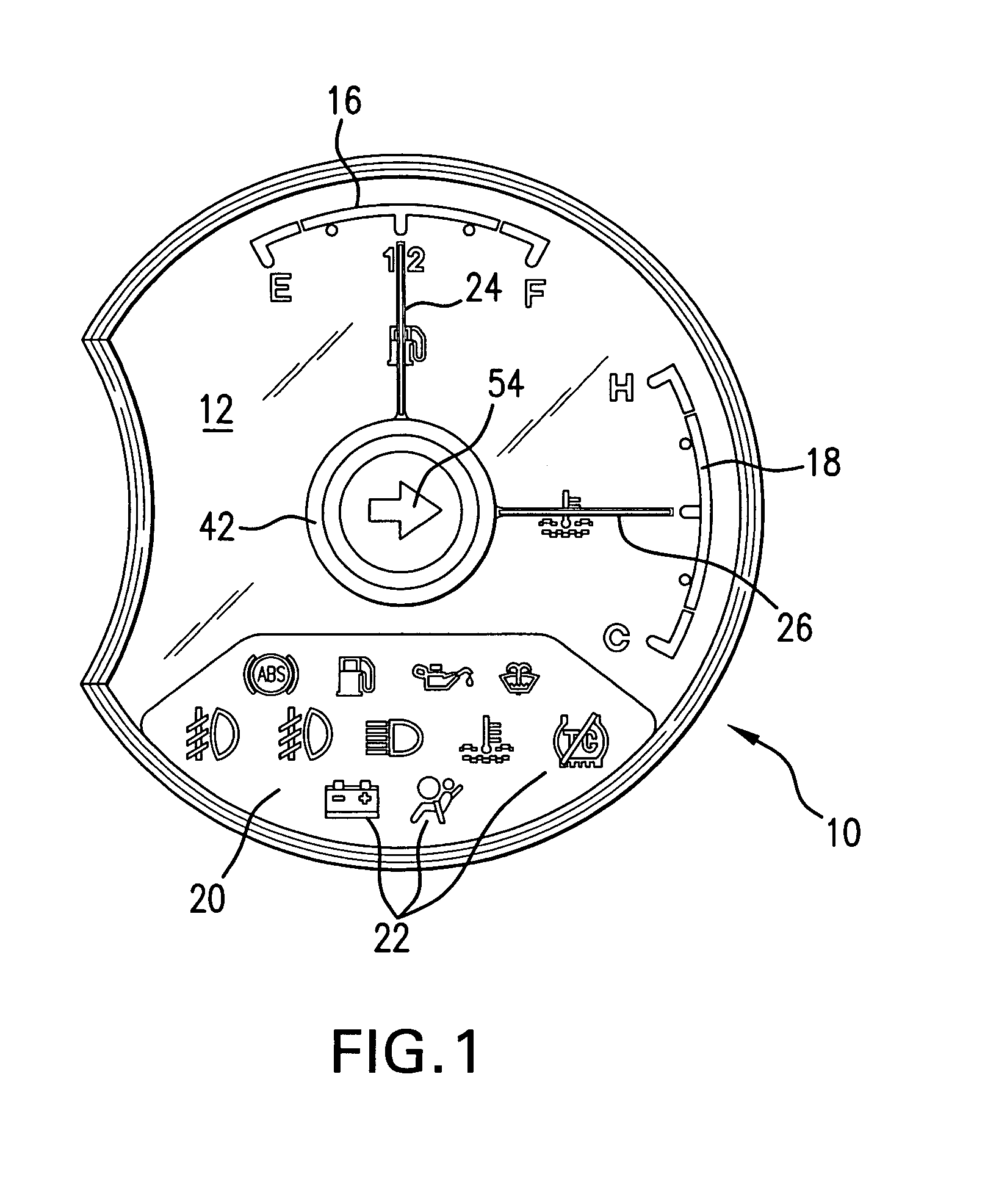
[0017]Referring now to FIGS. 1 and 4, a gauge or dial 10 has a front or display face 12 including indicia for identifying various vehicle parameters, and a rear face 14. In the illustrated example, there is a fuel display 16 and a temperature display 18. The dial is manufactured from transparent plastic. Ink of selected colors is printed on the plastic in the preferred pattern of the background field and display indicia. On a lower part of the dial there is a panel 20 tinted a different color than the background field, with various imprinted graphics or symbols 22. The symbols 22 include, for examples, a low-fuel indicator, a headlight high-beam indicator, a seat belt indicator, etc. for informing or warning a vehicle driver about various operating conditions.

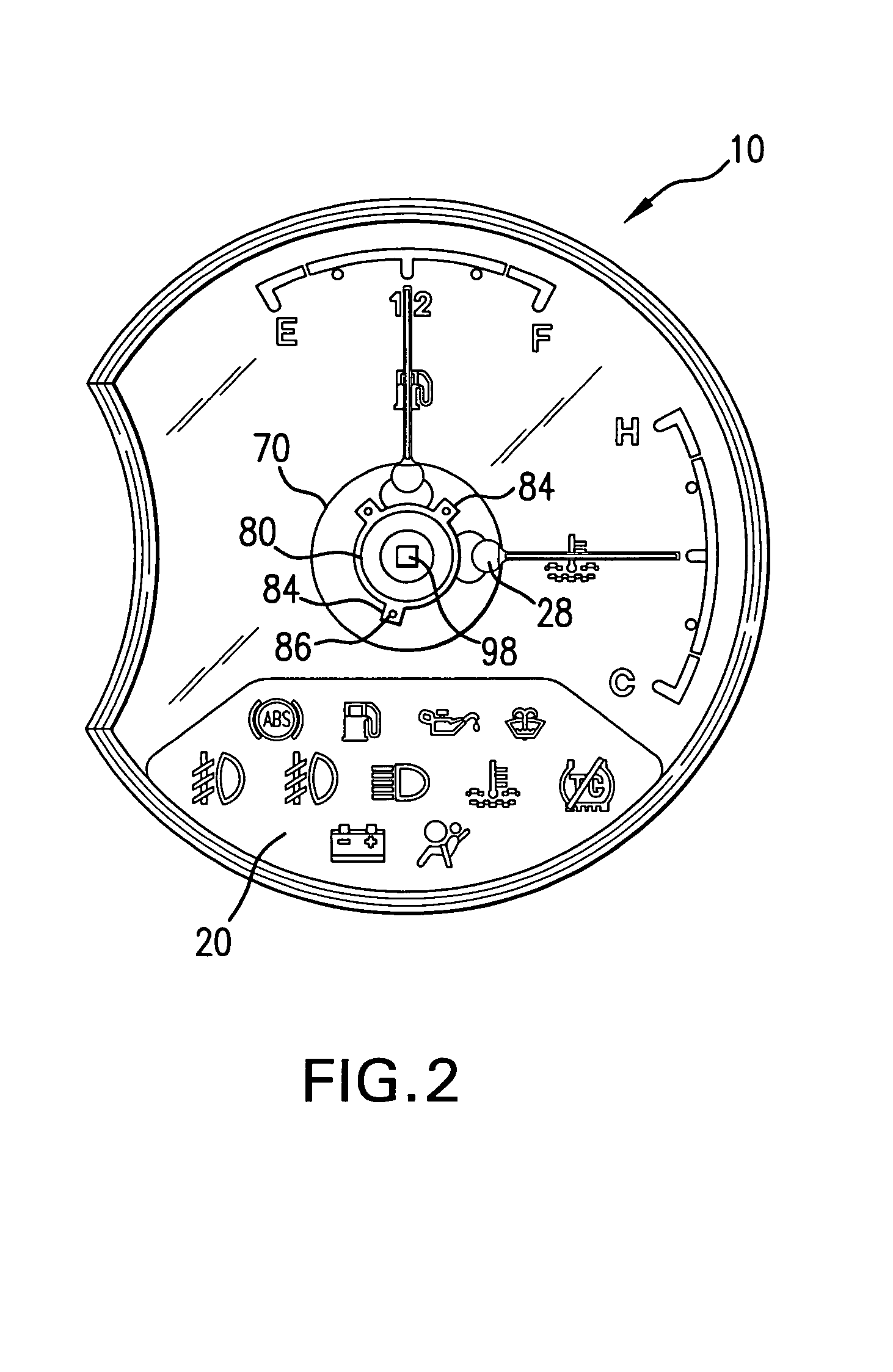
[0018]Pointers 24 and 26 are used to identify various measured values on the displays 16 and 18, respectively. As illustrated in FIGS. 3 and 4, the pointers have tail sections 28 formed with hollow cylindrical portions 30 that ...


PUM


Abstract

A gauge or dial has multiple displays for indicating various vehicle operating conditions. Pointers indicate a range of measured values on some of the displays. A fixed hub covers ends of the pointers where they connect with their drive shafts and extend through the dial. The hub has a display screen with a graphic or symbol imprinted on it. A conduit directly under the hub on an opposite side of the dial extends to a printed circuit board. A light emitting diode is mounted on the printed circuit board within the conduit. Light from the diode is reflected through the conduit to backlight the symbol on the display screen. Switching on and off of the diode is controlled in response to sensing or measurement of a vehicle condition or vehicle component operation, such as a turn signal.

Description

BACKGROUND OF THE INVENTION[0001]1. Field of the Invention[0002]This invention relates in general to illuminated instrument clusters in vehicles and more specifically to a compact consolidation of lighted indicators on a single dial or gauge.[0003]2. Discussion of Related Art[0004]Instrument clusters on the instrument panels of vehicles today often use backlighting to illuminate a dial or gauge and the associated pointer. More instruments and displays, such as for navigational, entertainment, radar and the like functions, are becoming increasingly practical and popular. This raises a need for more compact traditional vehicle information displays to allow or provide space for these other components. U.S. Pat. No. 6,382,127 illustrates one attempt to provide multiple information sources on a single dial face. Commonly assigned and co-pending U.S. patent application Ser. No. 10 / 824,472, filed Apr. 15, 2004, provides an example of how reflectors on the underside of the dials can be used...

Claims


Application Information

Patent Timeline
Patent Type & Authority Patents(United States)
IPC IPC(8): B60Q3/04G01D11/28
CPCB60Q3/044G01D11/28G01D7/04B60Q3/14B60K2370/698
Inventor VENKATRAM, SANJIV
Owner YAZAKI NORTH AMERICA
Why Eureka
Try Eureka