Driving system of motor vehicle

a technology of driving system and motor vehicle, which is applied in the direction of gearing control, gearing elements, gearing, etc., can solve the problems of large power loss in the driving system using the diesel engine as the driving power source, and achieve the effect of increasing or reducing the torque of the driving power source, and increasing or reducing the speed of rotation

Inactive Publication Date: 2006-06-27
TOYOTA JIDOSHA KK
View PDF18 Cites 9 Cited by
  • Summary
  • Abstract
  • Description
  • Claims
  • Application Information

AI Technical Summary

Benefits of technology

[0008]To accomplish the above object, there is provided according to the invention a driving system of a motor vehicle, comprising: (a) a driving power source that generates power, (b) a belt-and-pulley type continuously variable transmission that transmits the power received from the driving power source to a drive wheel while changing a first speed of rotation of an input shaft thereof to a second speed of rotation of an output shaft thereof, and (c) a speed changing mechanism provided between the driving power source and the continuously variable transmission so as to increase or reduce a speed of rotation of the driving power source during forward running of the vehicle.
[0009]In the driving system of the motor vehicle as described above, the speed changing mechanism is provided between the driving power source and the belt-and-pulley type continuously variable transmission, for increasing or reducing the speed of rotation of the driving power source during forward running of the vehicle. Thus, the speed changing mechanism is able to increase or reduce the torque of the driving power source and transmit the resulting torque to the continuously variable transmission. It is therefore possible to employ a common belt-and-pulley type continuously variable transmission for use with a plurality of types of driving power sources having different output characteristics, e.g., different torque characteristics, if, for example, the maximum torque applied to the continuously variable transmission is made substantially equal. This leads to a reduction in the overall manufacturing cost.
[0011]In the above-described driving system, the speed changing mechanism includes at least one planetary gear set and has a forward-drive / reverse-drive switching function. The driving system thus constructed is simpler in construction and is available at a reduced cost, as compared with the case where a speed changing device and a forward-drive / reverse-drive switching device are provided independently of or separately from each other.
[0013]In the driving system as described above, the driving power source is in the form of a diesel engine that generally outputs large torque at a lower rotational speed region than a gasoline engine. In the case where the diesel engine is used as the driving power source, the power of the diesel engine is transmitted to the belt-and-pulley type continuously variable transmission while the speed of rotation of the engine is increased by the speed changing mechanism, whereby the torque applied to the continuously variable transmission is reduced. Thus, the maximum torque transmitted from the diesel engine to the continuously variable transmission can be made equivalent to the maximum torque transmitted from the gasoline engine provided that the maximum power is substantially at the same level. Furthermore, the degree of variations in the torque is reduced as the torque is reduced with the increase in the rotational speed as described above. Thus, the belt-and-pulley type continuously variable transmission used in a diesel-engine vehicle can be made substantially as compact as that used in a gasoline-engine vehicle, and power loss due to large belt clamping force that would be otherwise required for the diesel-engine vehicle is reduced, thus assuring improved fuel economy.
[0018]For example, the belt-and-pulley type continuously variable transmission may include a pair of variable pulleys whose groove widths are variable, and a transmission belt that is wound around the variable pulleys. In operation, the continuously variable transmission transmits the power by utilizing friction generated between the transmission belt and the variable pulleys. Also, the continuously variable transmission is arranged to control the belt clamping force produced by one of the variable pulleys by means of, for example, a hydraulic cylinder, so as to avoid belt slippage, and control the groove width of the other variable pulley by means of, for example, a hydraulic cylinder, so as to establish a desired speed ratio.

Problems solved by technology

For these reasons, power loss in the driving system using the diesel engine as the driving power source is generally larger than that in the system using the gasoline engine.

Method used


Image

  • Driving system of motor vehicle
  • Driving system of motor vehicle
  • Driving system of motor vehicle

Examples


Embodiment Construction

[0030]A preferred embodiment of the, invention will be described in detail with reference to the accompanying drawings.

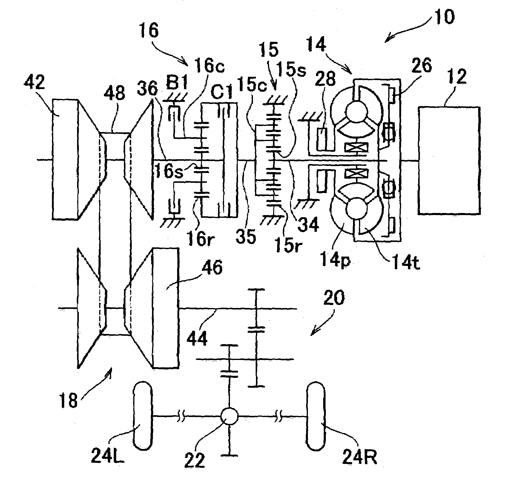
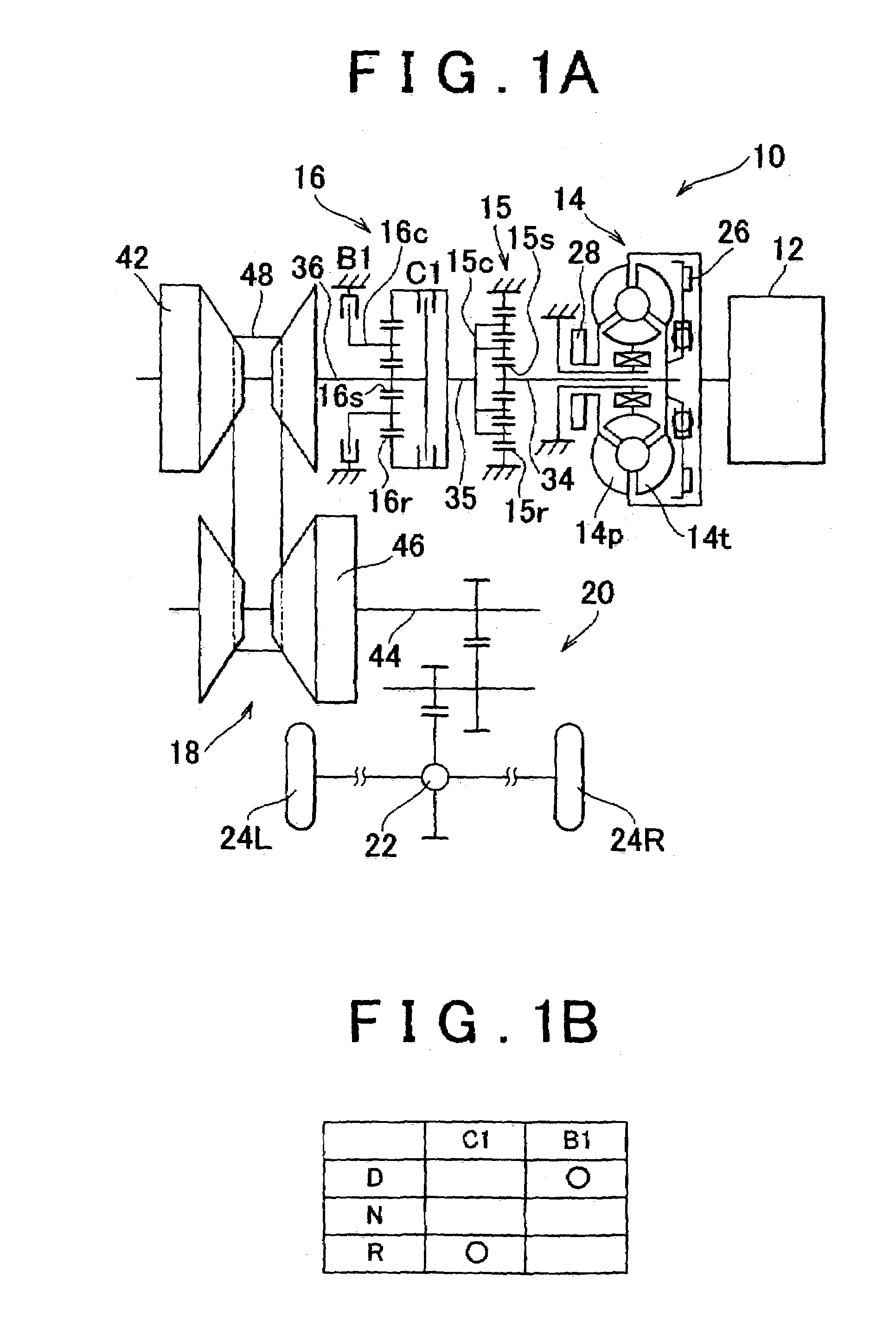
[0031]FIG. 1 schematically shows a driving system 10 of a motor vehicle to which the invention is applied. The vehicular driving system 10, which is of a lateral type, is favorably employed in a FF (front-engine, front-drive) vehicle. The driving system 10 includes a diesel engine 12 as a driving power source for running the vehicle. The power of the diesel engine 12 is transmitted to a differential gear unit 22 via a torque converter 14 as a hydraulic power transmitting device, an auxiliary speed changing device 15, a forward-drive / reverse-drive switching device 16, a belt-and-pulley type continuously variable transmission (CVT) 18, and a speed reducing gear train 20. The power thus transmitted to the differential gear unit 22 is then distributed to right and left drive wheels 24R, 24L.

[0032]The torque converter 14 includes a pump impeller 14p coupled to a cranksha...


PUM


Abstract

A driving system of a motor vehicle includes a driving power source that generates power, and a belt-and-pulley type continuously variable transmission that transmits the power received from the driving power source to drive wheels while changing a first speed of rotation of an input shaft thereof to a second speed of rotation of an output shaft thereof. The driving system further includes a speed changing mechanism provided between the driving power source and the continuously variable transmission so as to increase or reduce a speed of rotation of the driving power source during forward running of the vehicle.

Description

INCORPORATION BY REFERENCE[0001]The disclosure of Japanese Patent Application No. 2002-213024 filed on Jul. 22, 2002, including the specification, drawings and abstract, is incorporated herein by reference in its entirety.BACKGROUND OF THE INVENTION[0002]1. Field of the Invention[0003]The invention generally relates to a driving system of a motor vehicle, and in particular to a vehicular driving system that is easily applicable to a plurality of types of driving power sources having different output characteristics.[0004]2. Description of Related Art[0005]A driving system of a motor vehicle is known which is arranged to transmit rotary power generated by a driving power source to drive wheels while changing the speed of rotation by a belt-and-pulley type continuously variable transmission (CVT). Japanese Laid-open Patent Publication No. 11-182666 discloses one example of such a driving system in which a forward-drive / reverse-drive switching device of a planetary gear type is provide...

Claims


Application Information

Patent Timeline
Patent Type & Authority Patents(United States)
IPC IPC(8): F16H37/02F16H61/662B60W10/04B60W10/06B60W10/10B60W10/101
CPCF16H37/027F16H37/022Y10T477/688Y10T477/6237
Inventor HABUCHI, RYOJIYASUE, HIDEKI
Owner TOYOTA JIDOSHA KK
Why Eureka
Try Eureka