Bezel-button assembly and method

a technology of bezels and buttons, applied in the field of bezels, can solve the problem that the surface is a factor in the overall machine cost, and achieve the effect of reducing the cost of the overall machin

Inactive Publication Date: 2006-06-27
KEY PLASTICS
View PDF21 Cites 35 Cited by
  • Summary
  • Abstract
  • Description
  • Claims
  • Application Information

AI Technical Summary

Problems solved by technology

As a result, manufacturing of buttons and switches and their placement into the dashboards or other surfaces is a factor in the overall machine cost.
While such a system does allow buttons to operate within the bezel, some drawbacks may exist.

Method used


Image

  • Bezel-button assembly and method
  • Bezel-button assembly and method
  • Bezel-button assembly and method

Examples


Embodiment Construction

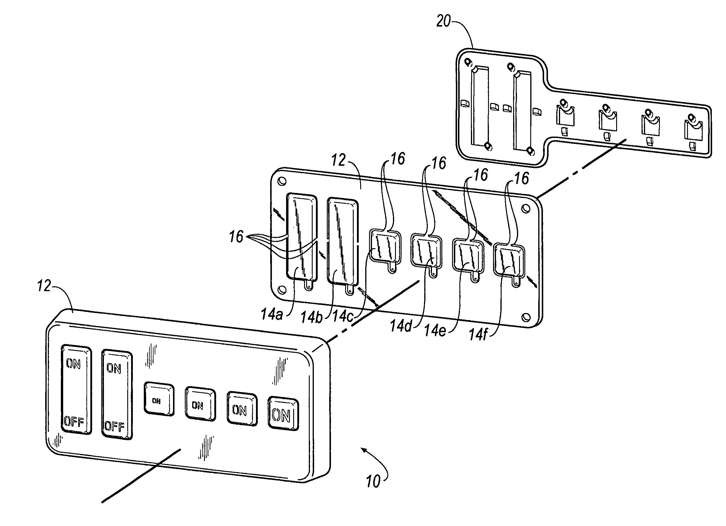
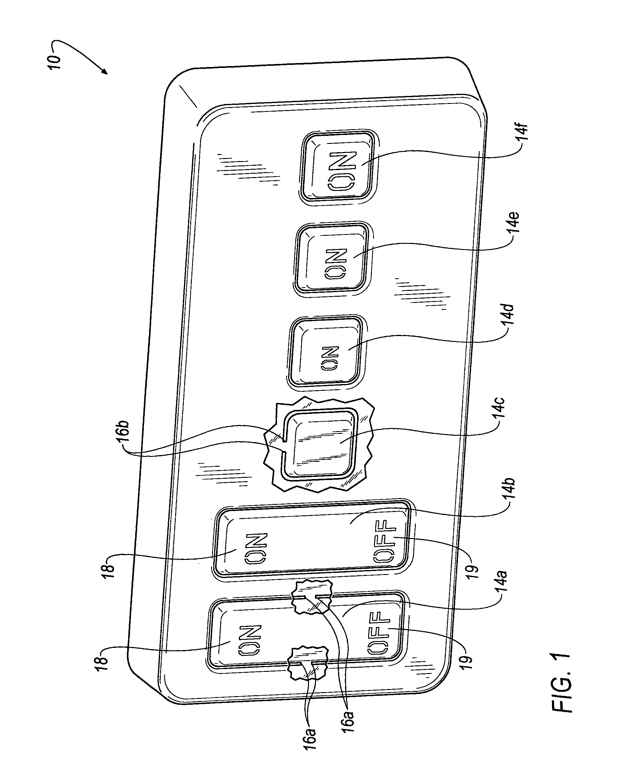
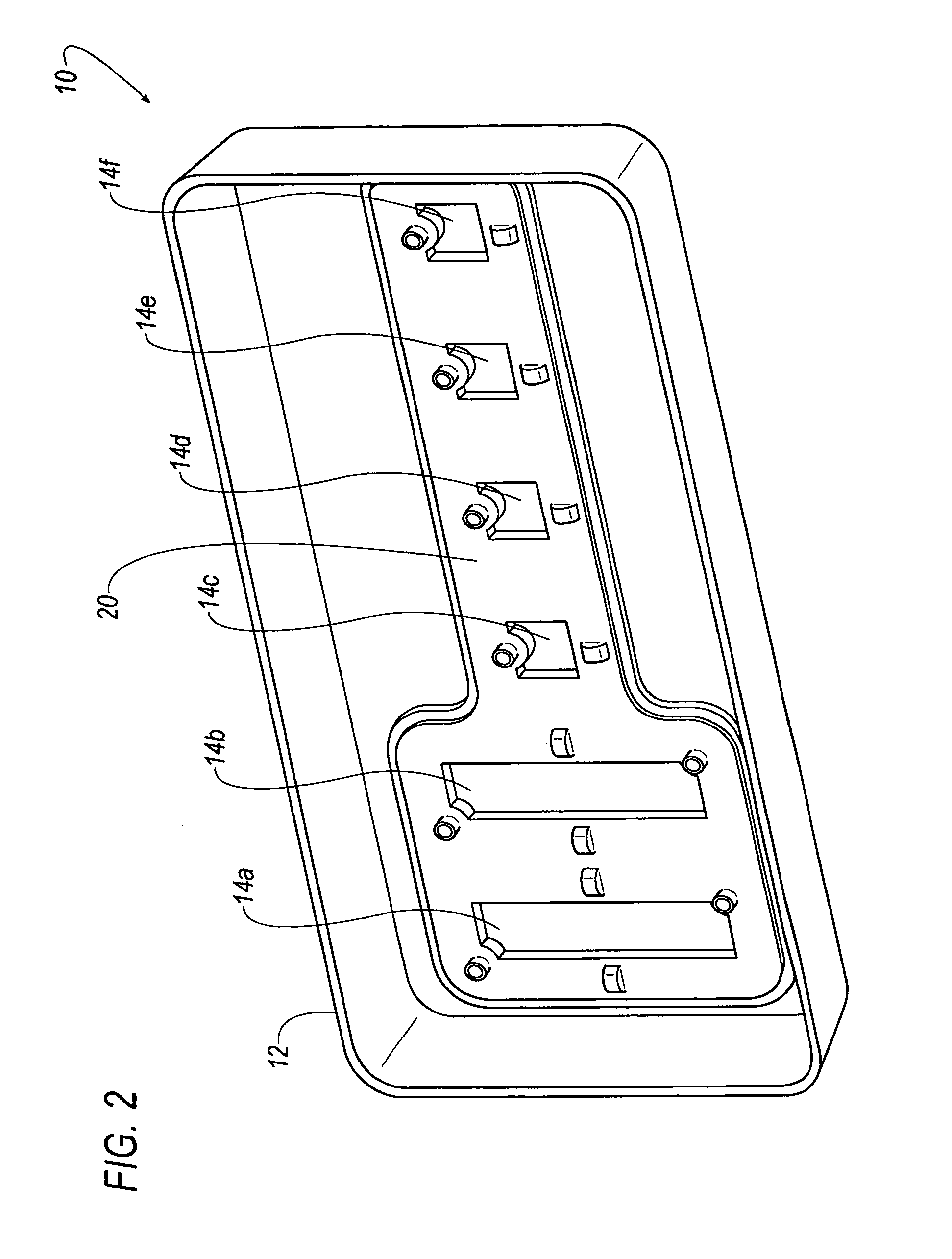
[0013]Referring now to FIGS. 1 and 2, a button bezel assembly 10 is shown including a bezel portion 12; a plurality of buttons, for example 14a, 14b, 14c, 14d, 14e and 14f, that are disposed in the bezel portion 12; and a layer 20 attached or connected adjacent to bezel portion 12.

[0014]In an embodiment of the invention, one or more hinge members 16 may be integrally formed with the buttons 14 and bezel 12. For instance, each of the buttons 14 may be connected to the bezel portion 12 by hinge members, such as those illustratively represented as elements 16a and 16b in the cut-away segments of FIG. 1. It is however noted that multiple hinge member combinations (as shown) are not required. Moreover, hinge members are not required in all embodiments and may be eliminated from inclusion with respect the entire assembly or one or more buttons 14. Nonetheless, when present, the hinge members may serve the added purpose of retaining the buttons 14 in a desired position during the formation...


PUM


Abstract

A bezel-button assembly comprising at least one button connected to a bezel. The button is moveable between a first position and at least a second position. An elastic layer connects the bezel to the button and is adapted to provide at least a partial mechanical bias of the button toward the first position. A method for forming a bezel-button assembly is also disclosed.

Description

FIELD OF THE INVENTION[0001]The present invention relates generally to a bezel including those with an integrated button.BACKGROUND OF THE INVENTION[0002]Switches and buttons are a part of everyday machine operation. Vehicle dashboards and other devices commonly include a multitude of switches and buttons for performing a multitude of operations. As a result, manufacturing of buttons and switches and their placement into the dashboards or other surfaces is a factor in the overall machine cost. Conventional manufacturing of buttons or other switch devices commonly incorporates a moveable button portion disposed in an outer shell or bezel, which surrounds the button. The bezel may provide an aesthetically pleasing or other suitable support surface while having the structure to allow a user to actuate the button. While such a system does allow buttons to operate within the bezel, some drawbacks may exist. For example, conventional manufacturing of button bezels typically requires multi...

Claims


Application Information

Patent Timeline
Patent Type & Authority Patents(United States)
IPC IPC(8): H01H9/00H01H13/06
CPCH01H13/06H01H2235/008H01H2229/046H01H2223/034
Inventor WESTON, MARKDOBSON, STANLEY
Owner KEY PLASTICS
Why Eureka
Try Eureka