
Electroluminescence light emitting steel

a technology of light-emitting steel and electroluminescence, which is applied in the direction of instruments, discharge tubes, luminescent indicating devices, etc., can solve the problems of monotonous and insipid, and el sheet also has the disadvantage of not attracting attention

Inactive Publication Date: 2006-06-27
TOMY CO LTD
View PDF56 Cites 5 Cited by
  • Summary
  • Abstract
  • Description
  • Claims
  • Application Information

AI Technical Summary

Problems solved by technology

However, since the EL light emitting sheet disclosed in Patent Document 1 only emits light, it is monotonous and insipid.
Such an EL sheet also has a disadvantage of not attracting attention in case of being used as, for example, a signboard or the like.

Method used


Image

  • Electroluminescence light emitting steel
  • Electroluminescence light emitting steel
  • Electroluminescence light emitting steel

Examples


Embodiment Construction

[0027]Hereinafter, the preferred embodiments of the present invention will be described in detail by reference to the attached drawings.

A. EL Light Emitting Sheet

[0028]1. Whole Configuration

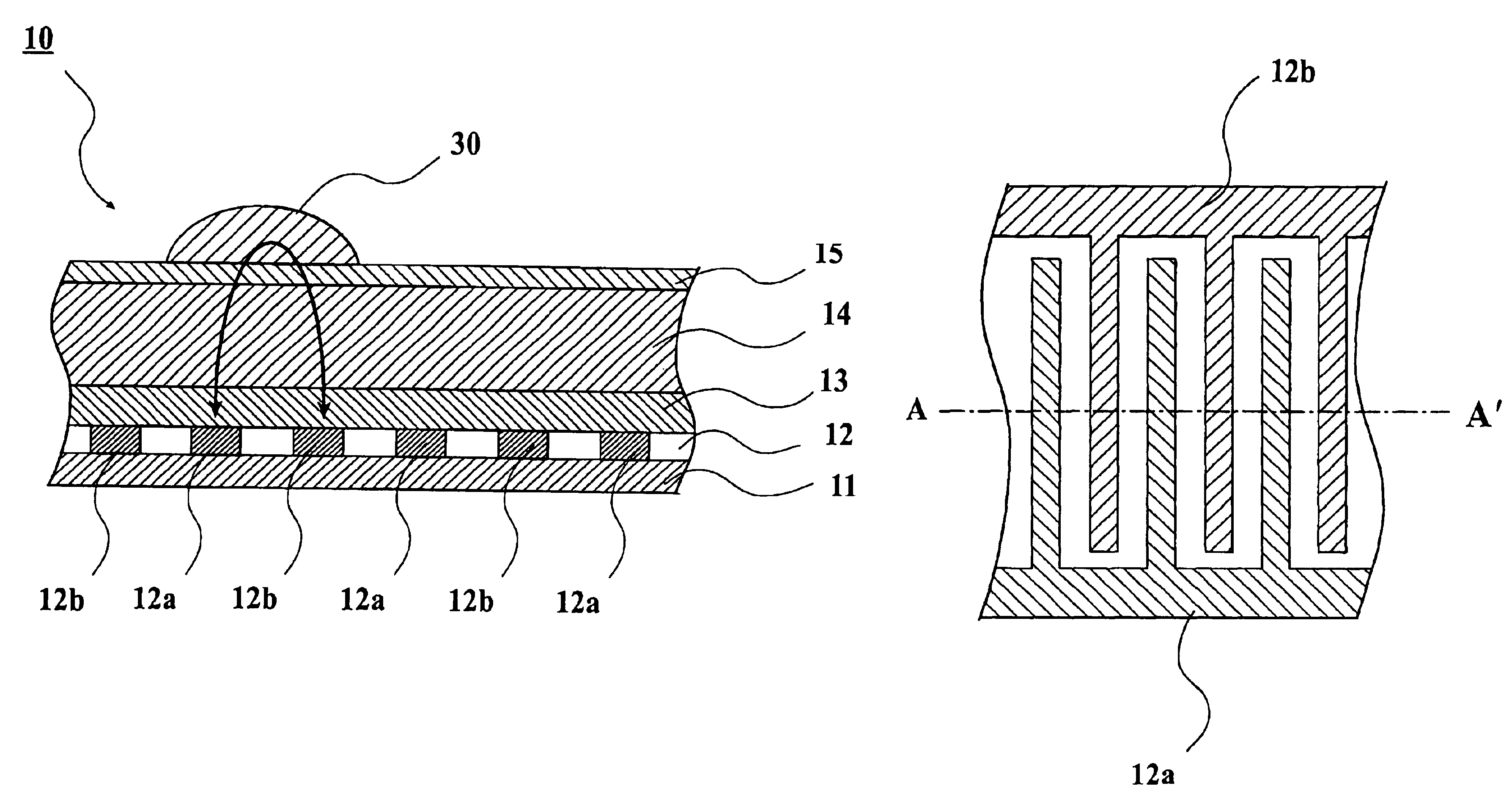
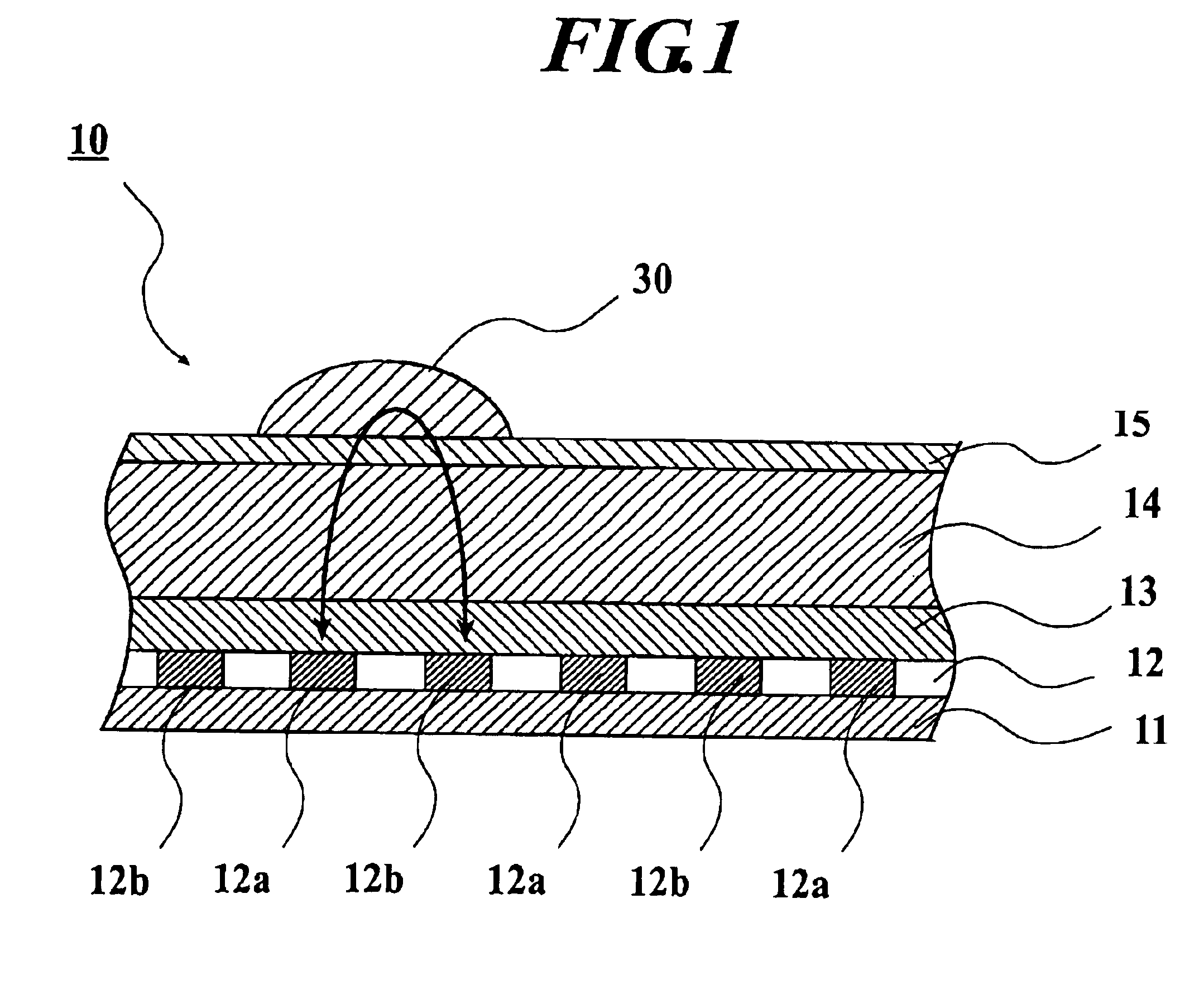
[0029]FIG. 1 is an enlarged sectional view of a principal part of an EL light emitting sheet 10 to which the present invention is applied. In FIG. 1, the EL light emitting sheet 10 is formed by laminating a base layer 11, an electrode layer (electrode section) 12, a waterproof layer 13, an EL light-emitting layer 14 and a top coat layer 15 in this order.

[0030]2. Detailed Configuration

[0031](1) Base Layer 11

[0032]The base layer 11 is made of an insulating material such as polyethylene terephthalate (PET) or the like. The base layer 11 may be configured as a base film (substrate sheet). In this case, the base film is made of a transparent or opaque resin. As the resin in this case, for example, PET is used. The base layer 11 may be made of glass.

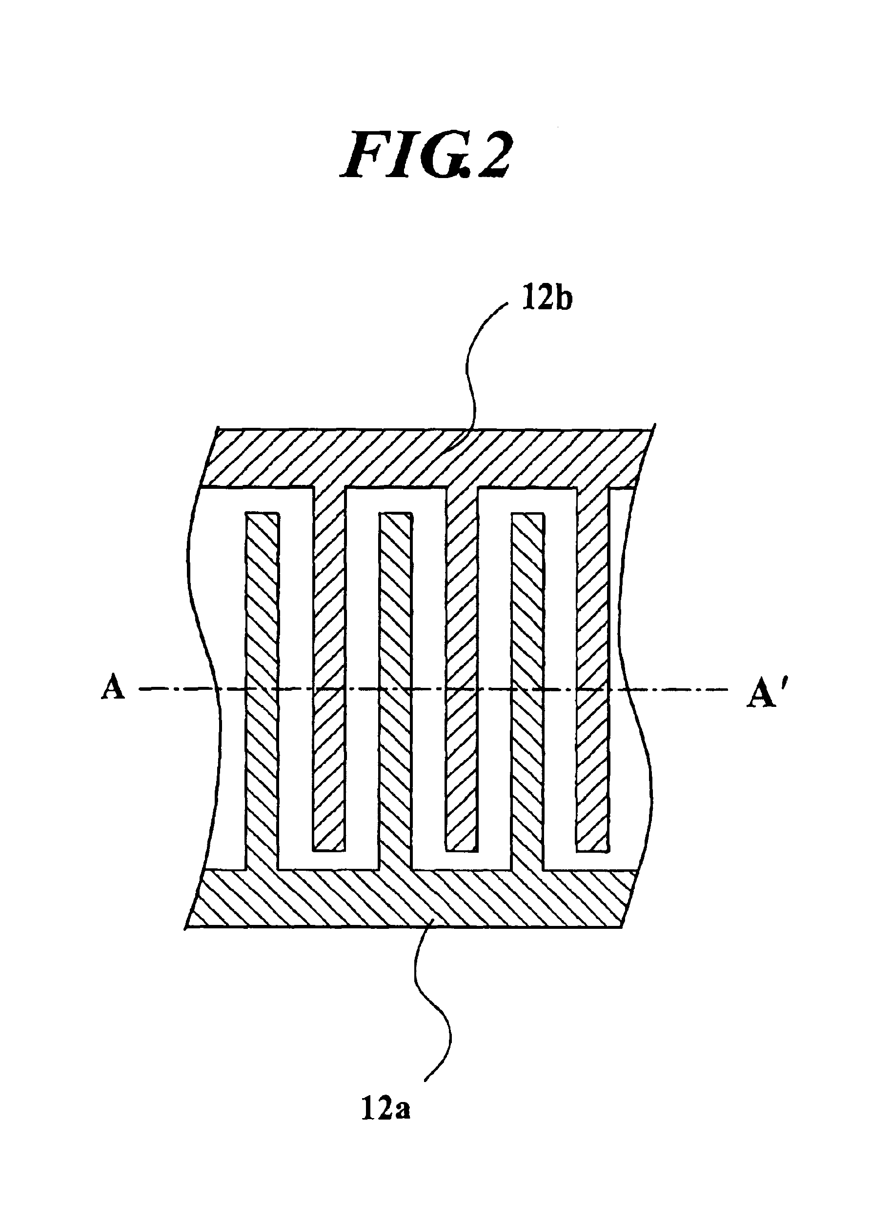
[0033](2) Electrode Layer 12

[0034]The electrode layer...


PUM


Abstract

An EL emitting sheet realizing various changes of light emission. The EL emitting sheet includes: a light-emitting layer containing electroluminescence light-emitting elements therein; and an electrode section having a plurality of electrode pairs which is disposed with a predetermined arrangement, wherein each of the electrode pairs includes first and second electrodes which are electrically separated from each other with a spacing region and disposed in one surface side of the light-emitting layer with a predetermined arrangement.

Description

BACKGROUND OF THE INVENTION[0001]1. Field of the Invention[0002]The present invention relates to an electroluminescence light emitting sheet.[0003]2. Related Art[0004]An electroluminescence, hereinafter, which may be referred to EL simply, material is known as one of light emitting materials. Various types of EL light emitting sheets have been developed and put to practical use. The EL light emitting sheet is generally formed by laminating a first electrode, a light-emitting layer, an insulating layer, i.e., a light reflecting layer, a second electrode and a protective layer in order. Generally, by applying an alternating voltage (AC voltage) between the fist electrode and the second electrode, a fluorescent material, i.e., EL light emitting elements, in the light-emitting layer emits light.[0005]As another type of EL light emitting sheet, one having peculiar operation and effects is known (see, for example, Patent Document 1: Japanese Patent Laid-Open Publication No. Hei 8-153582)....

Claims


Application Information

Patent Timeline
Patent Type & Authority Patents(United States)
IPC IPC(8): H01J1/62H01J63/04A63H33/00A63H33/22G09F13/22G09G3/30H05B33/26
CPCA63H33/22H05B33/26G09G3/30
Inventor WATANABE, KIMITAKAYAMANAKA, HIROYUKI
Owner TOMY CO LTD
Features
  • Generate Ideas
  • Intellectual Property
  • Life Sciences
  • Materials
  • Tech Scout
  • Unparalleled Data Quality
  • Higher Quality Content
  • 60% Fewer Hallucinations
Learn More