Inflator

a technology of inflator and propellant, which is applied in the direction of vehicle components, pedestrian/occupant safety arrangements, weapons, etc., can solve the problems of increasing the complexity, weight, and expense of the inflator, and reducing the safety of passengers and passengers

Inactive Publication Date: 2006-07-11
AUTOMOTIVE SYST LAB
View PDF13 Cites 55 Cited by
  • Summary
  • Abstract
  • Description
  • Claims
  • Application Information

AI Technical Summary

Benefits of technology

[0007]Use of a smokeless gas generant composition allows the inflator to operate without the need for a filter to remove particulate materials from the inflation gas. In addition, the inflator described herein provides a continuous fluid path for inflation gas that extends from the interior of the second baffle, through the fluid channel formed between the baffles, out the first baffle apertures and into the fluid channel formed between the first baffle and the housing, and exiting the inflator via the housing apertures. Thus, a tortuous flow path is provided for cooling the inflation gasses, obviating the need for a filter for cooling the gases.

Problems solved by technology

Inhalation by a vehicle occupant of particulates generated by propellant combustion during airbag activation can be hazardous.
However, inclusion of the filter in the inflator increases the complexity, weight, and expense of the inflator.

Method used


Image

  • Inflator
  • Inflator
  • Inflator

Examples


Embodiment Construction

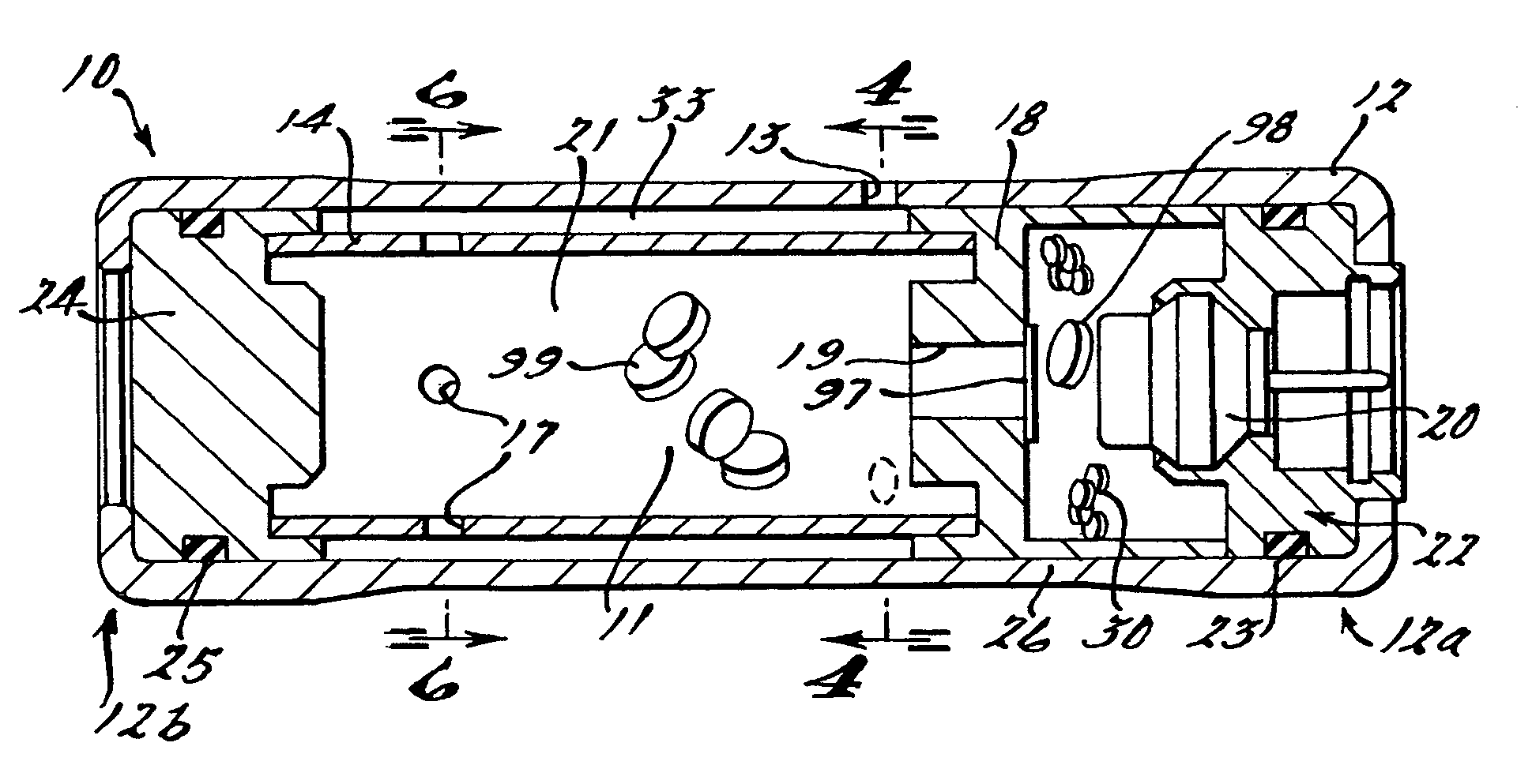
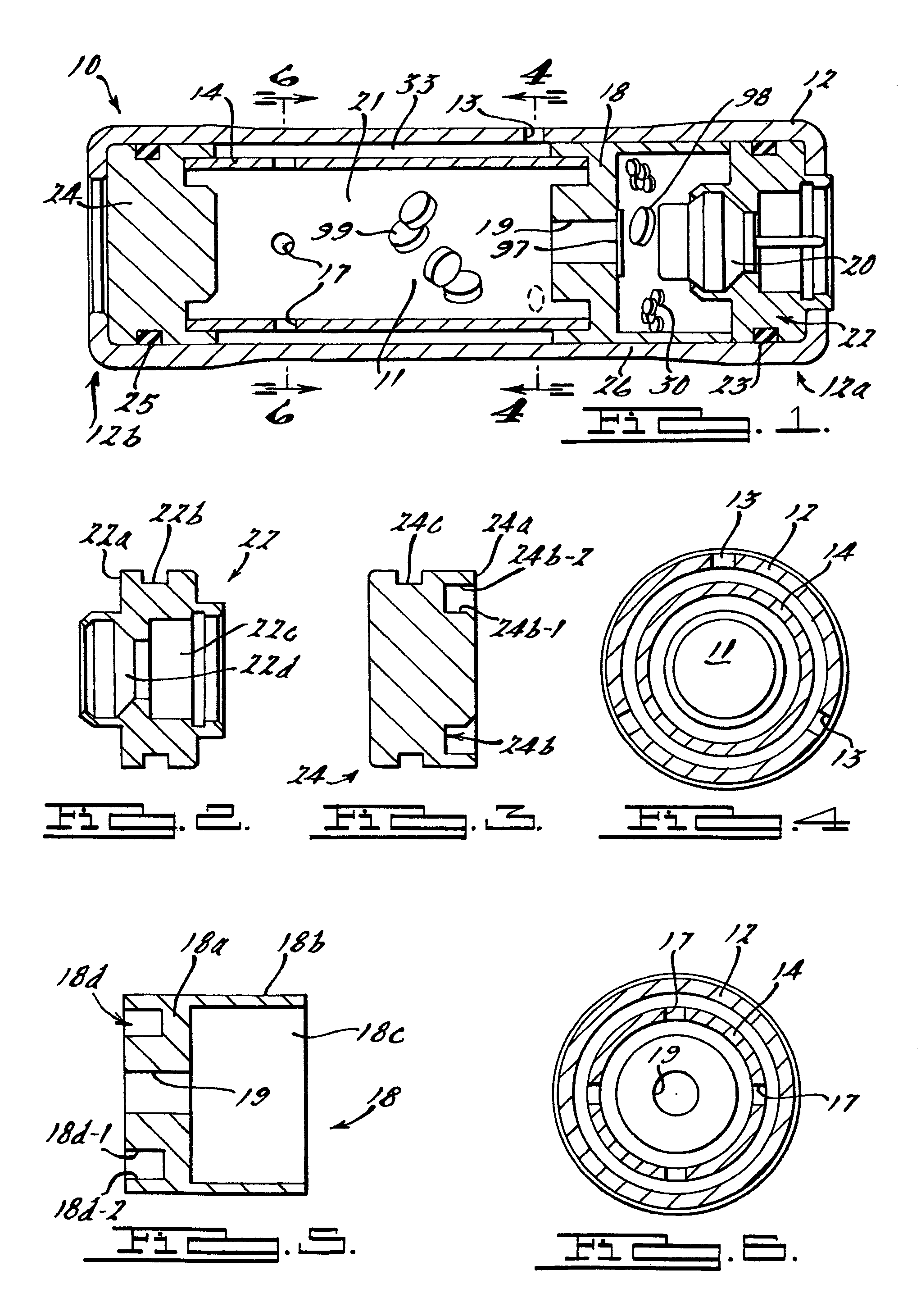
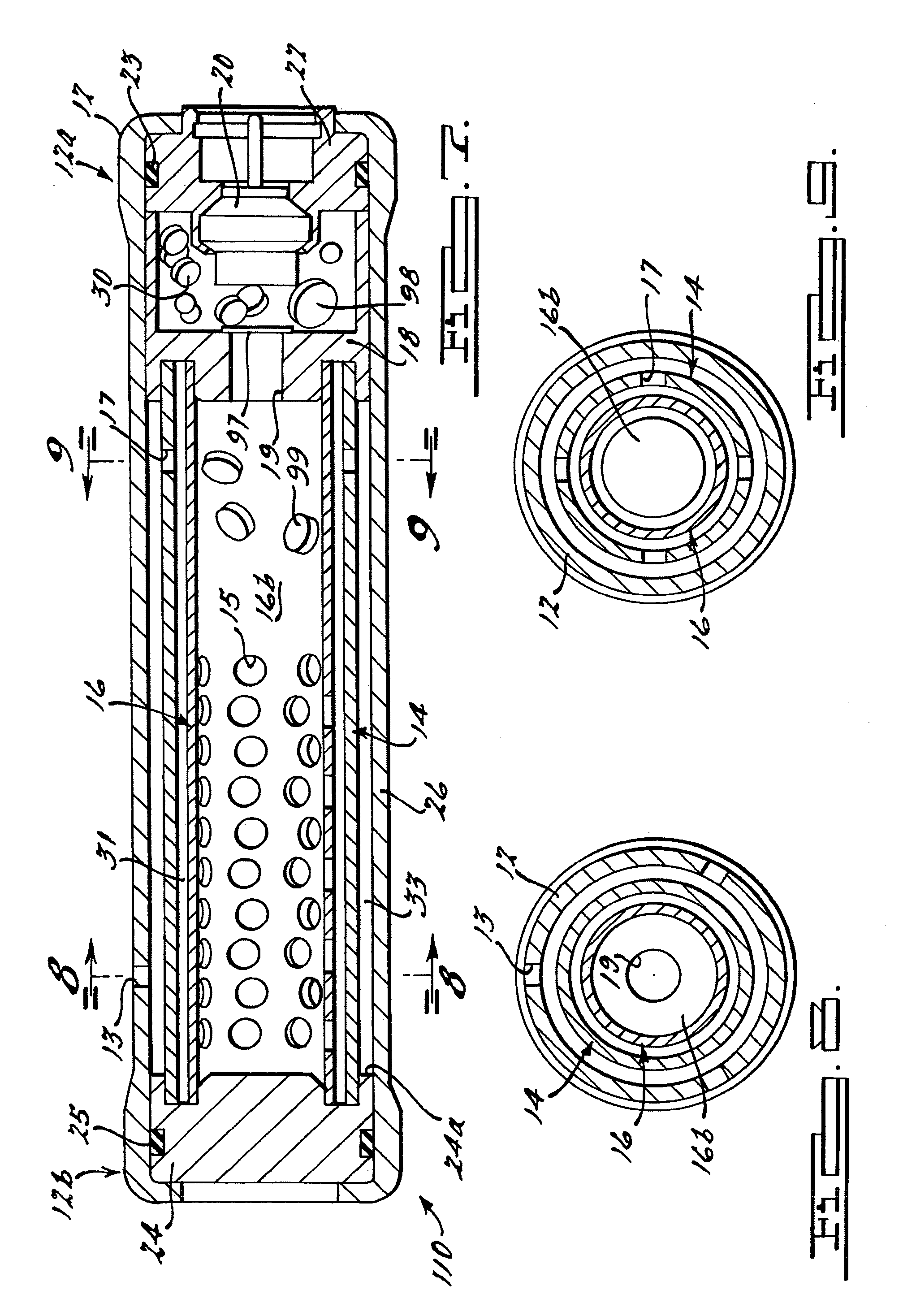
[0018]FIG. 1 shows one embodiment of an inflator 10 in accordance with the present invention. Inflator 10 includes a substantially cylindrical housing 12 having a pair of opposed ends 12a, 12b and a wall 26 extending between the ends to define a housing interior cavity 21. Housing 12 is made from a metal or metal alloy and may be a cast, stamped, extruded, or otherwise metal-formed. A first end closure 22 is secured to end 12a of housing 12, and a second end closure 24 is secured to an opposite end 12b of housing 12 using one or more known methods. In FIG. 1, ends 12a and 12b of housing 12 are crimped over portions of first and second end closures 22, 24 to secure the end closures within the housing.

[0019]Referring to FIGS. 1 and 2, first end closure 22 has formed therein a peripheral shoulder 22a, a peripheral cavity 22b, a central cavity 22c, and a central orifice 22d for receiving end portions of the inflator components therein. Referring to FIG. 3, second end closure 24 has form...


PUM


Abstract

An inflator (10) for a vehicle occupant restraint system. The inflator (10) includes a housing (12) having apertures (13) formed therealong to enable fluid communication between an interior of the housing (12) and an exterior of the housing. A first baffle (14) is positioned in the housing interior. The baffle (14) is spaced apart from the housing (12) to define a fluid channel (33) therebetween in communication with the housing apertures (13). The baffle (14) includes a first opening (17) for fluid communication between an interior of the baffle (14) and the fluid channel (33), and an open end portion for fluid communication between the baffle interior and the baffle exterior. A spacer (18) positioned in the housing interior cavity defines an enclosure (18c) and includes an aperture (19) formed therein for fluid communication between the enclosure (18c) and the open end portion of the baffle. A gas generant (30) is positioned within the spacer enclosure (18c). The gas generant (30) may be a smokeless gas generant composition. An initiator (20) is coupled to the housing (12) for initiating combustion of the gas generant (30) upon activation of the inflator. The inflator (10) provides a continuous, tortuous fluid path through the fluid channel (33) for cooling inflation gases. In addition, the use of a smokeless gas generant composition allows the inflator (10) to operate without the need for a filter to remove particulate materials from the inflation gas.

Description

CROSS-REFERENCE TO RELATED APPLICATIONS[0001]This application claims the benefit of provisional application Ser. No. 60 / 530215 filed on Dec. 17, 2003.BACKGROUND OF THE INVENTION[0002]The present invention relates generally to inflators for use in inflatable occupant restraint systems in motor vehicles and, more particularly, to inflators that do not incorporate a filter for removal of particulates from combustion gases and cooling of the gases.[0003]Installation of inflatable occupant restraint systems, generally known as “airbags,” as standard equipment in all new vehicles has intensified the search for smaller, lighter and less expensive restraint systems. Accordingly, since the inflator used in such systems tends to be the heaviest and most expensive component, there is a need for a lighter and less expensive inflator.[0004]A typical inflator includes a cylindrical steel or aluminum housing having a diameter and length related to the vehicle application and characteristics of a g...

Claims


Application Information

Patent Timeline
Patent Type & Authority Patents(United States)
IPC IPC(8): B60R21/26B60R21/264
CPCB60R21/264B60R21/2644
Inventor MCCORMICK, DAVID M.
Owner AUTOMOTIVE SYST LAB
Why Eureka
Try Eureka