Aerodynamic drag reduction apparatus for gap-divided bluff bodies such as tractor-trailers

a technology of aerodynamic drag reduction and bluff body, which is applied in the direction of roofs, transportation and packaging, vehicle arrangements, etc., can solve the problems of increasing the aerodynamic drag of the tractor-trailer, increasing the aerodynamic and increasing the aerodynamic drag. , to achieve the effect of reducing the aerodynamic drag of the bluff body and preventing cross-flow

Inactive Publication Date: 2006-07-11
LAWRENCE LIVERMORE NAT SECURITY LLC
View PDF6 Cites 60 Cited by
  • Summary
  • Abstract
  • Description
  • Claims
  • Application Information

AI Technical Summary

Benefits of technology

[0011]One aspect of the present invention includes an apparatus for reducing the aerodynamic drag of a bluff-bodied vehicle in a flowstream, the bluff-bodied vehicle of a type having a leading portion and a trailing portion connected to the leading portion with a gap therebetween defining a recirculation zone, comprising: a baffle assembly adapted to span a width of the gap between the leading and trailing portions so as to impede cross-flow through the gap, and having means for automatically adjusting the span of the baffle assembly for variations in the gap width when the leading and trailing portions pivot relative to each other.
[0012]Another aspect of the present invention includes an apparatus for reducing the aerodynamic drag of a bluff body in a flowstream, the bluff body of a type having a leading portion and a trailing portion connected to the leading portion with a gap therebetween, comprising: means securable to the bluff body for bounding at least one of two transversely opposite open ends thereof when secured to the bluff body to impede airflow into the gap through said transversely opposite open ends.

Problems solved by technology

As the aerodynamic drag experienced by a vehicle increases, the fuel costs also correspondingly increase due to the greater energy required to overcome the drag.
Moreover, for bluff bodies comprising multi-linked or otherwise gap-spaced unit components with gaps between adjacent units, the aerodynamic drag can be even greater when the recirculation zone formed in the gap is disrupted by a cross-flow through the gap.
However, even small amounts of cross-flow present a compromise in the ability of the vortical structure to prevent airflow from further entering the gap, and can thereby increase the aerodynamic drag on the tractor-trailer 100.
The stabilizer plate, however, only partially closes the gap, which is an imperfect situation since some air will be forced from one of the divided vortex regions to the other by pressure differences therebetween.
By having such an opening through the gap a cross-flow is allowed to form, especially under side wind conditions, which can disturb the vortical structures to adversely impact aerodynamic drag.

Method used


Image

  • Aerodynamic drag reduction apparatus for gap-divided bluff bodies such as tractor-trailers
  • Aerodynamic drag reduction apparatus for gap-divided bluff bodies such as tractor-trailers
  • Aerodynamic drag reduction apparatus for gap-divided bluff bodies such as tractor-trailers

Examples


Embodiment Construction

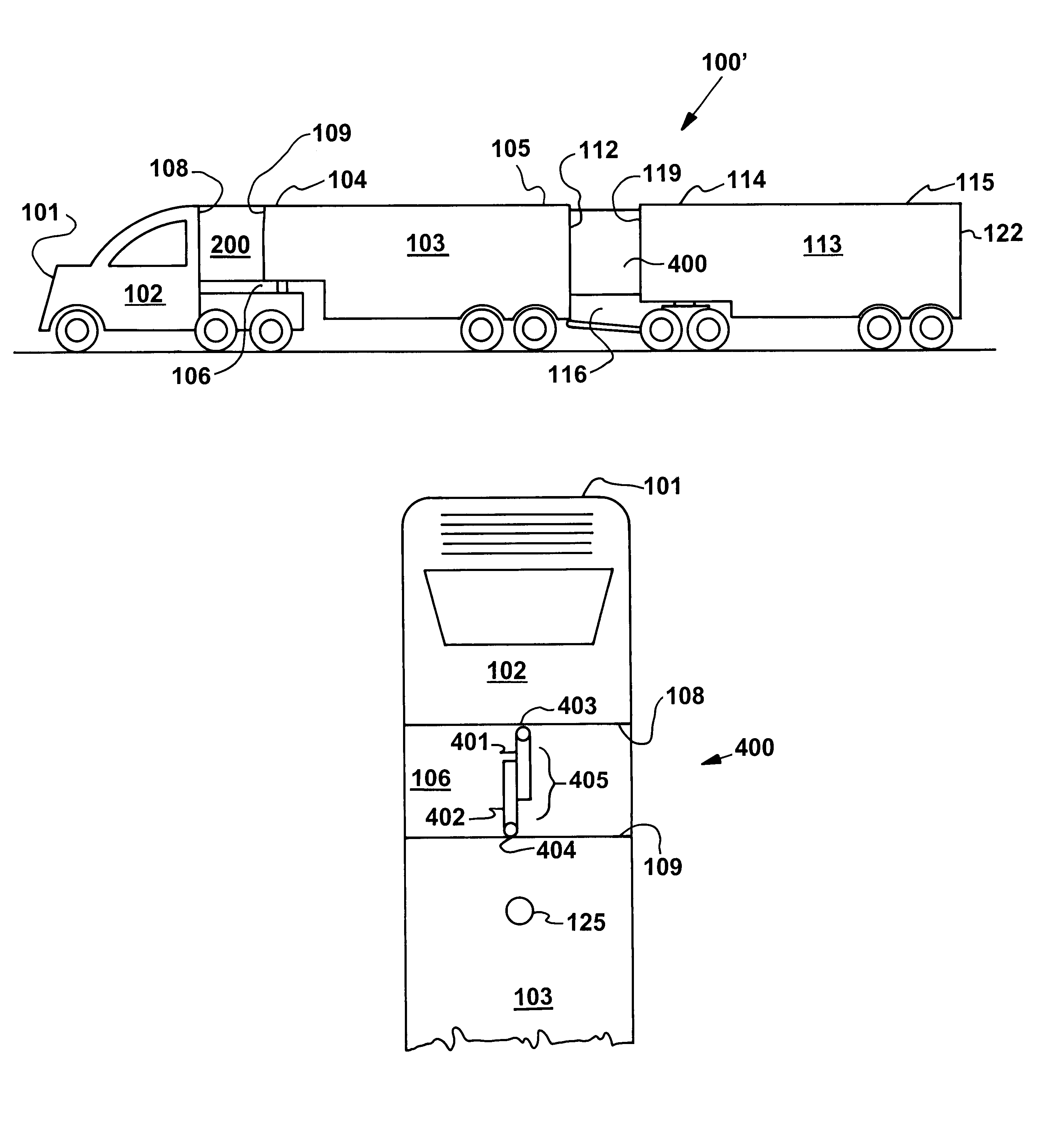
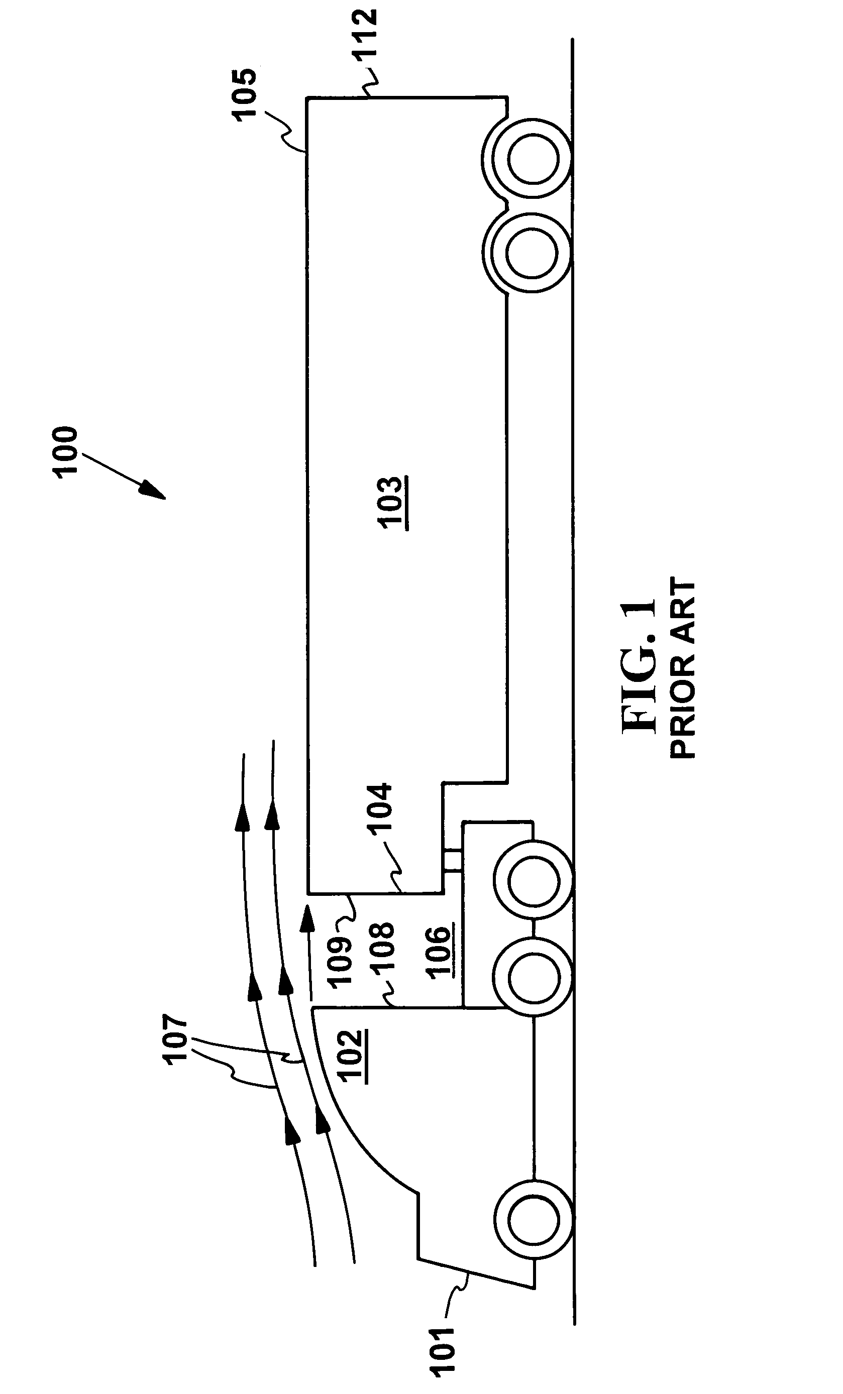
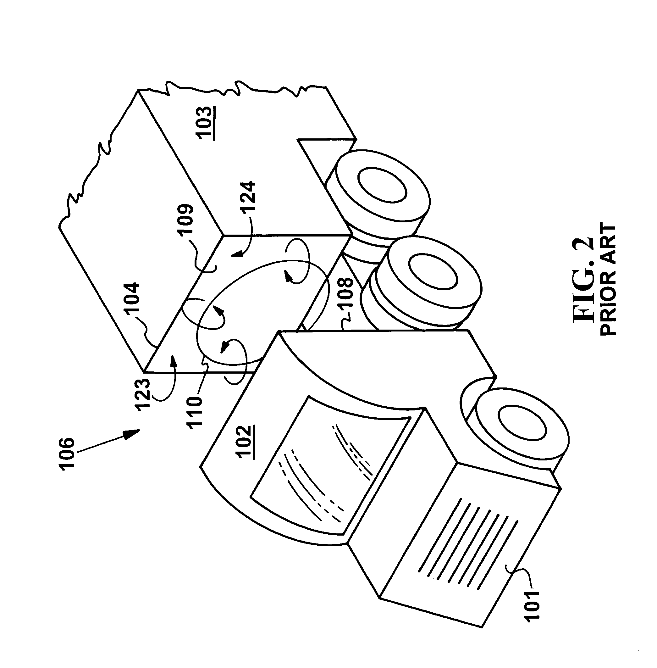
[0027]The present invention is directed to an aerodynamic drag reduction apparatus for use with a gap-spaced bluff body or bluff body vehicle having a leading portion and at least one trailing portion linked or otherwise connected to each other to form a gap between adjacent portions, such as for example a tractor-trailer or other multi-unit or towing vehicle arrangement. As discussed in the Background, a recirculation zone is formed in the gap which can be destabilized by a cross-flow therein or therethrough. The various embodiments of the present invention operate to maintain the stability of the recirculation zone by spanning the entire width of the gap to impede cross-flow therethrough, and thereby reduce the net aerodynamic drag on the bluff body. It is also notable that the leading and trailing portions together indicate the direction of the flowstream, i.e. the tractor or leading portion is upstream of the trailer or trailing portion.

[0028]The present invention may be utilize...


PUM


Abstract

An apparatus for reducing the aerodynamic drag of a bluff-bodied vehicle such as a tractor-trailer in a flowstream, the bluff-bodied vehicle of a type having a leading portion, a trailing portion connected to the leading portion, and a gap between the leading and trailing portions defining a recirculation zone. The apparatus is preferably a baffle assembly, such as a vertical panel, adapted to span a width of the gap between the leading and trailing portions so as to impede cross-flow through the gap, with the span of the baffle assembly automatically adjusting for variations in the gap width when the leading and trailing portions pivot relative to each other.

Description

I. CLAIM OF PRIORITY IN PROVISIONAL APPLICATION[0001]This application claims priority in provisional application filed on May 30, 2003, entitled “Drag Reduction of a Heavy Vehicle by Stabilizing the Gap Flow between the Tractor and Trailer through the Use of a Vertical Plate” Ser. No. 60 / 474980, by Jason M. Ortega et al, and incorporated herein by reference.[0002]The United States Government has rights in this invention pursuant to Contract No. W-7405-ENG48 between the United States Department of Energy and the University of California for the operation of Lawrence Livermore National Laboratory.II. FIELD OF THE INVENTION[0003]The present invention relates to aerodynamic drag reduction methods and devices. The invention relates more particularly to an apparatus for reducing the aerodynamic drag of a bluff bodied vehicle caused by a gap between leading and trailing portions of the bluff bodied vehicle, by baffling and thus impeding cross-flow through the gap.III. BACKGROUND OF THE INV...

Claims


Application Information

Patent Timeline
Patent Type & Authority Patents(United States)
IPC IPC(8): B62D35/00
CPCB62D35/001
Inventor ORTEGA, JASON M.SALARI, KAMBIZ
Owner LAWRENCE LIVERMORE NAT SECURITY LLC
Why Eureka
Try Eureka