Bidirectional shaving implement

a shaving implement and bidirectional technology, applied in the direction of metal working devices, etc., can solve the problems of cumbersome repositioning of the shaving implement, increased time required for shaving operation, and difficulty in shaving hard to reach areas

Inactive Publication Date: 2006-08-08
EDGEWELL PERSONAL CARE BRANDS LLC
View PDF17 Cites 115 Cited by
  • Summary
  • Abstract
  • Description
  • Claims
  • Application Information

AI Technical Summary

Problems solved by technology

When shaving large areas, like the surface of a leg, the need to reposition the shaving implement increases the time required to complete a shaving operation.
Another difficulty can occur when shaving hard to reach areas that have complex contours, such as, for example, an armpit.
It can become cumbersome to reposition the razor prior to each stroke.
However, due to the blades facing away from each other, and the fact that no friction reducing materials were employed in the razor, significant amounts of drag and thereby discomfort resulted as the razor was drawn across the user's skin.
Another problem associated with prior art razors configured in the above-described manner was that they either did not pivot at all, or the range of pivotal motion, relative to the handle on which the cartridge was mounted, was insufficient to allow the cutting edges of the razor blades to follow the contours of the user's skin and to allow for an effective reversal of the cutting direction.
Another drawback associated with the aforementioned prior art, outwardly facing, opposed blade systems is that during a shaving operation, the line of action of the force that moves the blades in the direction of the cut pushes the blade.
This has the potential to cause blade chatter or overturning moments.
Either of these occurrences can result in an uncomfortable shaving experience.
Another difficulty encountered when using the prior art razors sometimes occurred when a user reversed the stroke direction.
Often this resulted in a slightly sideways movement of the blades against the user's skin.
Because the cutting edges of the blades were generally completely exposed this motion resulted in nicking or cutting of the skin.

Method used


Image

  • Bidirectional shaving implement
  • Bidirectional shaving implement
  • Bidirectional shaving implement

Examples


Embodiment Construction

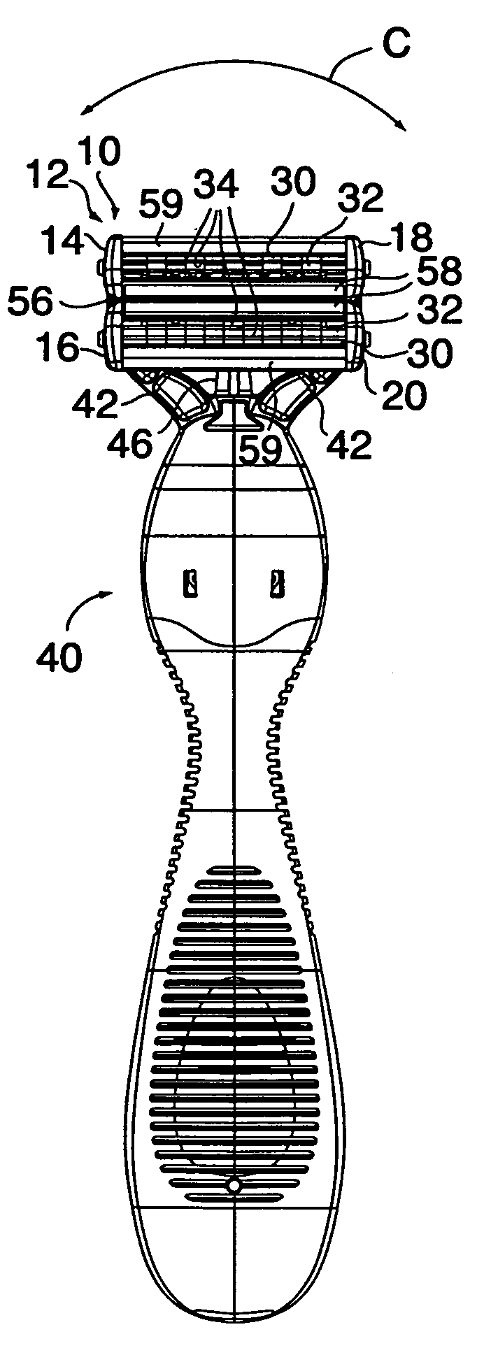
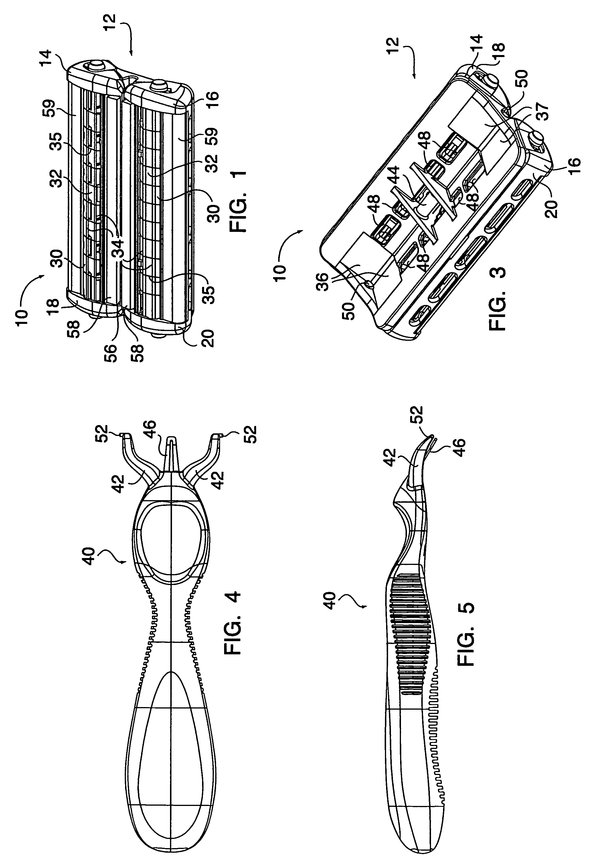
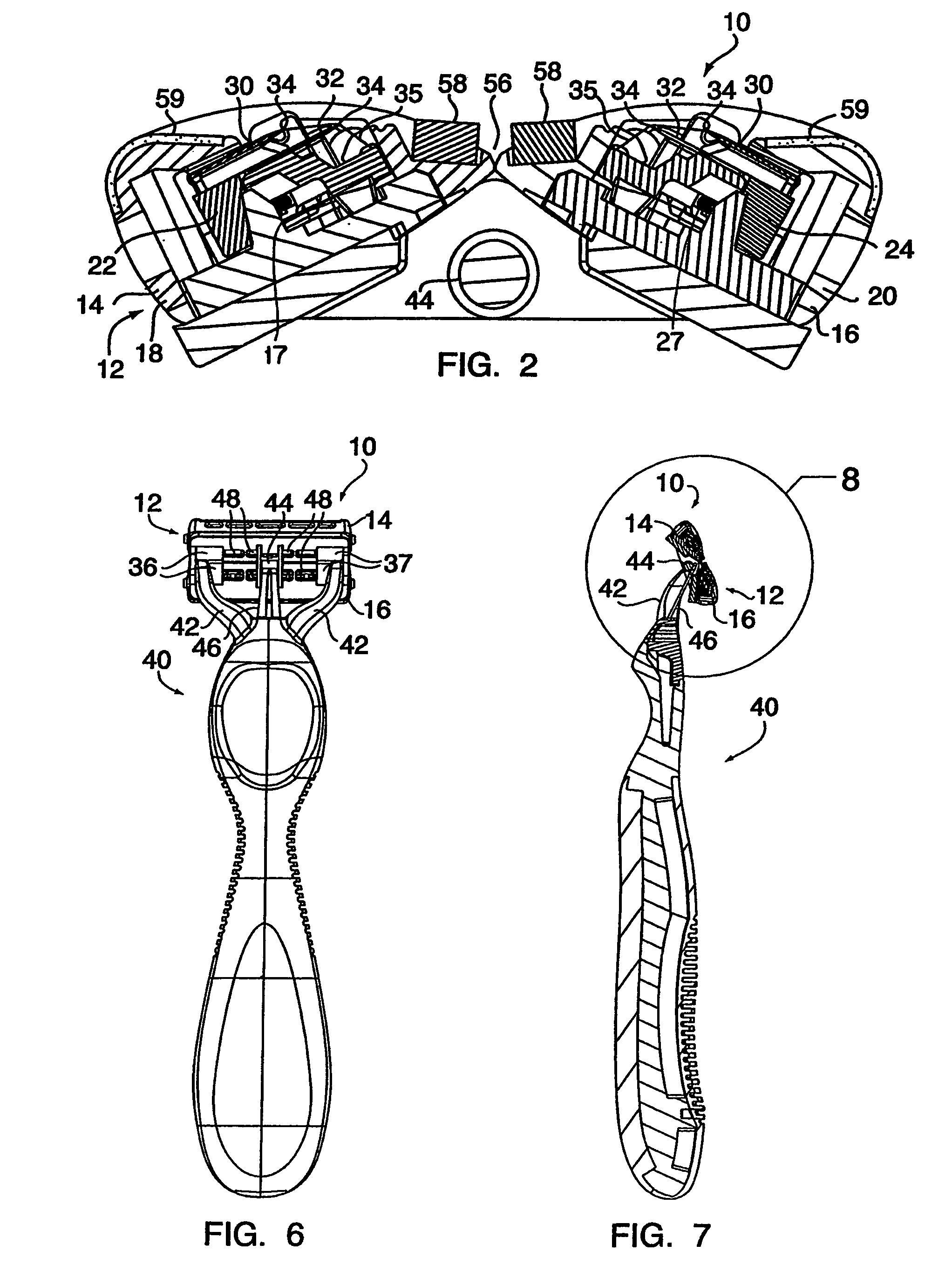
[0026]As shown in FIGS. 1–3, a razor cartridge embodying the present invention and generally designated by the reference number 10 includes a platform portion 12 having first and second cartridge sections, 14 and 16 respectively, mounted thereon. The first cartridge section 14 includes a first housing 18, and the second cartridge section 16 includes a second housing 20. A first blade retainer 22, best seen in FIG. 2, is positioned in the first housing 18, and a second blade retainer 24 is positioned in the second housing 20. The first and second blade retainers, 22 and 24 respectively, are each movable between a neutral position, where the blade retainers are positioned closest to the leading edges of the first and second blade housings, 18 and 20 respectively, and a retracted position where the blade retainers are located away from the leading edges. A spring 17, 27 is positioned in each cartridge section to normally urge the blade retainers toward the neutral position. The first a...


PUM


Abstract

In a razor cartridge, a platform portion has a first cartridge section that includes at least one first pair of razor blades position therein. Each of the first pair or razor blades has an at least partially exposed cutting edge. A second cartridge section is also provided and is coupled to the platform portion. The second cartridge section includes at least one pair of second razor blades positioned therein, each of the second pair of razor blades also has an at least partially exposed cutting edge. The razor cartridge can be mounted either temporarily or permanently to a handle and the cutting edges of each of the first and second pair of razor blades face one another so that during a shaving operation, the razor cartridge can cut hair when drawn over a user's skin in either of two generally opposite directions.

Description

CROSS REFERENCE TO RELATED PATENT APPLICATIONS[0001]This patent application is a continuation-in-part of U.S. patent application Ser. No. 10 / 686,992, entitled, “Bidirectional Shaving Cartridge and Razor Including Same,” filed on Oct. 16, 2003, now abandoned, claiming priority to Provisional Patent Application No. 60 / 420,273 filed on Oct. 21, 2002, the disclosures of which are incorporated in their entirety by reference herein.FIELD OF THE INVENTION[0002]The present invention generally relates to wet shaving implements and is more particularly directed to a shaving implement able to cut hair when drawn over a user's skin in either of two generally opposite directions.BACKGROUND OF THE INVENTION[0003]Wet shaving razors typically incorporate razor cartridges that have one or more razor blades mounted in a housing with each razor blade having an exposed cutting edge. Generally, the razor can only be drawn in a single direction over a user's skin to cut hair and must be repositioned for ...

Claims


Application Information

Patent Timeline
Patent Type & Authority Patents(United States)
IPC IPC(8): B26B21/52B26B21/22B26B21/14B26B21/40
CPCB26B21/222B26B21/225B26B21/522B26B21/4006B26B21/521B26B21/227
Inventor COFFIN, DAVID C.NICOLOSI, RANDYPENNELLA, ANDREW J.RICHARD, PAUL D.
Owner EDGEWELL PERSONAL CARE BRANDS LLC
Why Eureka
Try Eureka