Golf club heads

a golf club and head technology, applied in the field of golf club heads, can solve the problems of reducing the inertial moment adversely affecting the twist resistance property of the golf club head b>1/b>, etc., to improve the striking effect reduce the weight, and increase the inertial momentum of the golf club head

Inactive Publication Date: 2006-08-15
FUSHENG PRECISION
View PDF9 Cites 54 Cited by
  • Summary
  • Abstract
  • Description
  • Claims
  • Application Information

AI Technical Summary

Benefits of technology

[0006]An object of the present invention is to provide a golf club head including a heel with a reduced weight to shift the center of gravity of the golf club head toward the toe of the golf club head, thereby increasing the inertial momentum of the golf club head and improving the striking effect of the golf club head.
[0007]Another object of the present invention is to provide a golf club head with improved shock-absorbing capacity and strengthened structure.
[0008]A further object of the present invention is to provide a golf club head allowing a relatively wide adjusting range for the center of gravity.

Problems solved by technology

As a result, the inertial moment of the golf club head 1 is reduced and the twist-resisting property of the golf club head 1 is adversely affected.

Method used


Image

  • Golf club heads
  • Golf club heads
  • Golf club heads

Examples


first embodiment

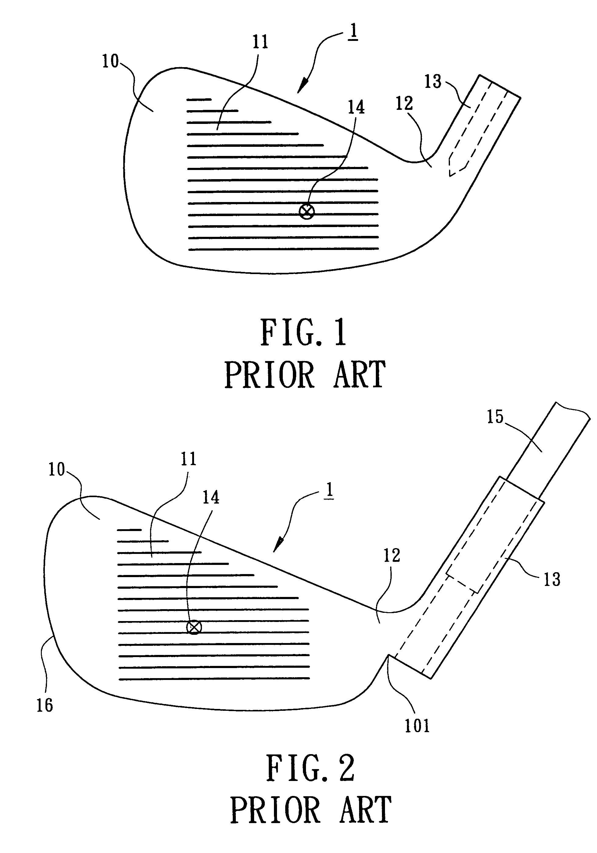
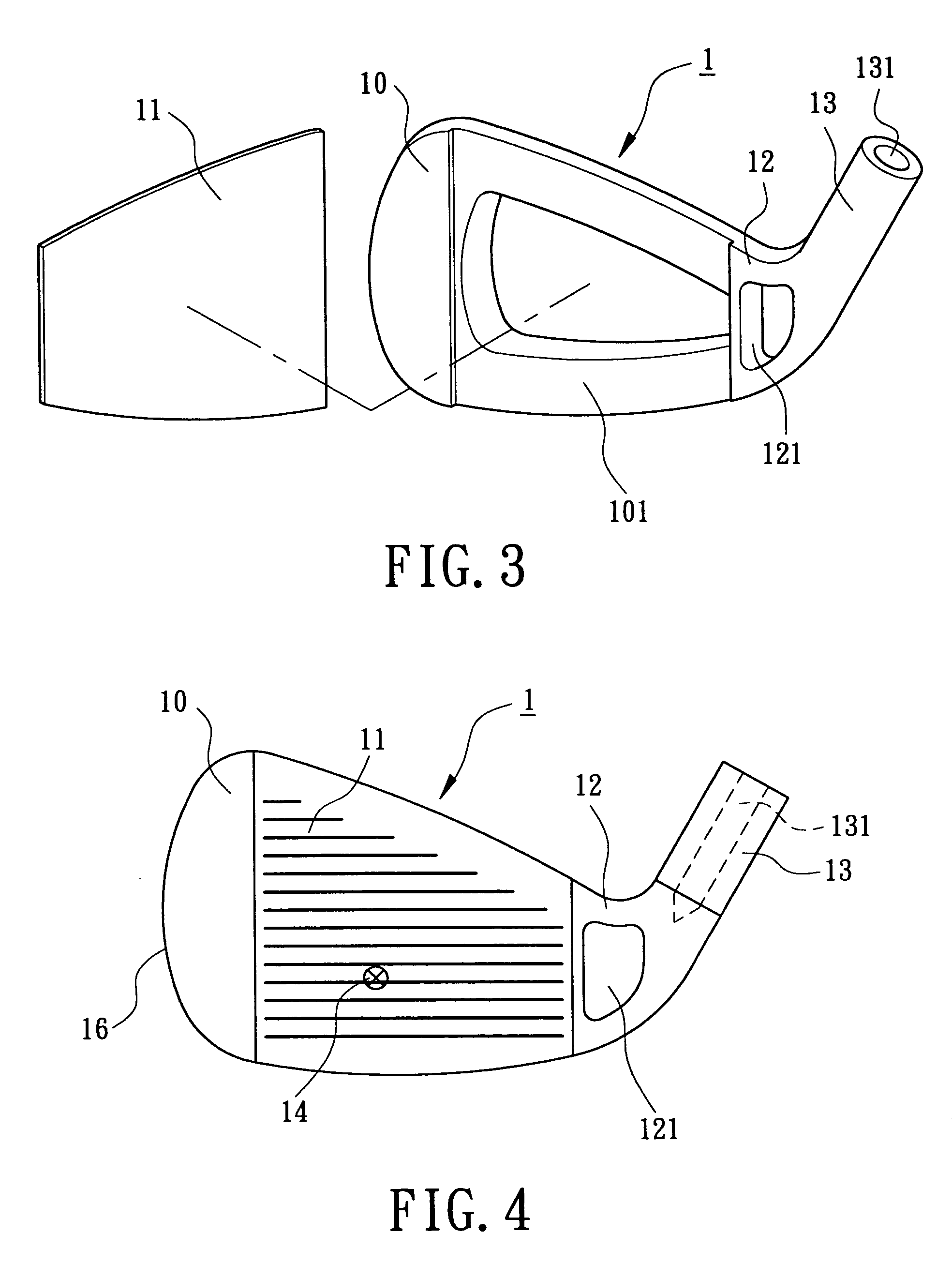
[0034]Referring to FIGS. 3 and 4, a golf club head 1 in accordance with the present invention is made of metal or alloy and includes a golf club head body 10, a striking plate 11 for striking a golf ball, a neck or hosel 13, and a heel 12 between the hosel 13 and the golf club head body 10. The golf club head body 10 includes an engaging portion 101. The striking plate 11 is integrally formed with the engaging portion 101 of the golf club head body 10. Alternatively, the striking plate 11 may be engaged with the engaging portion 101 of the golf club head body 10 by means of insertion, pressing, brazing, welding, screwing, etc.

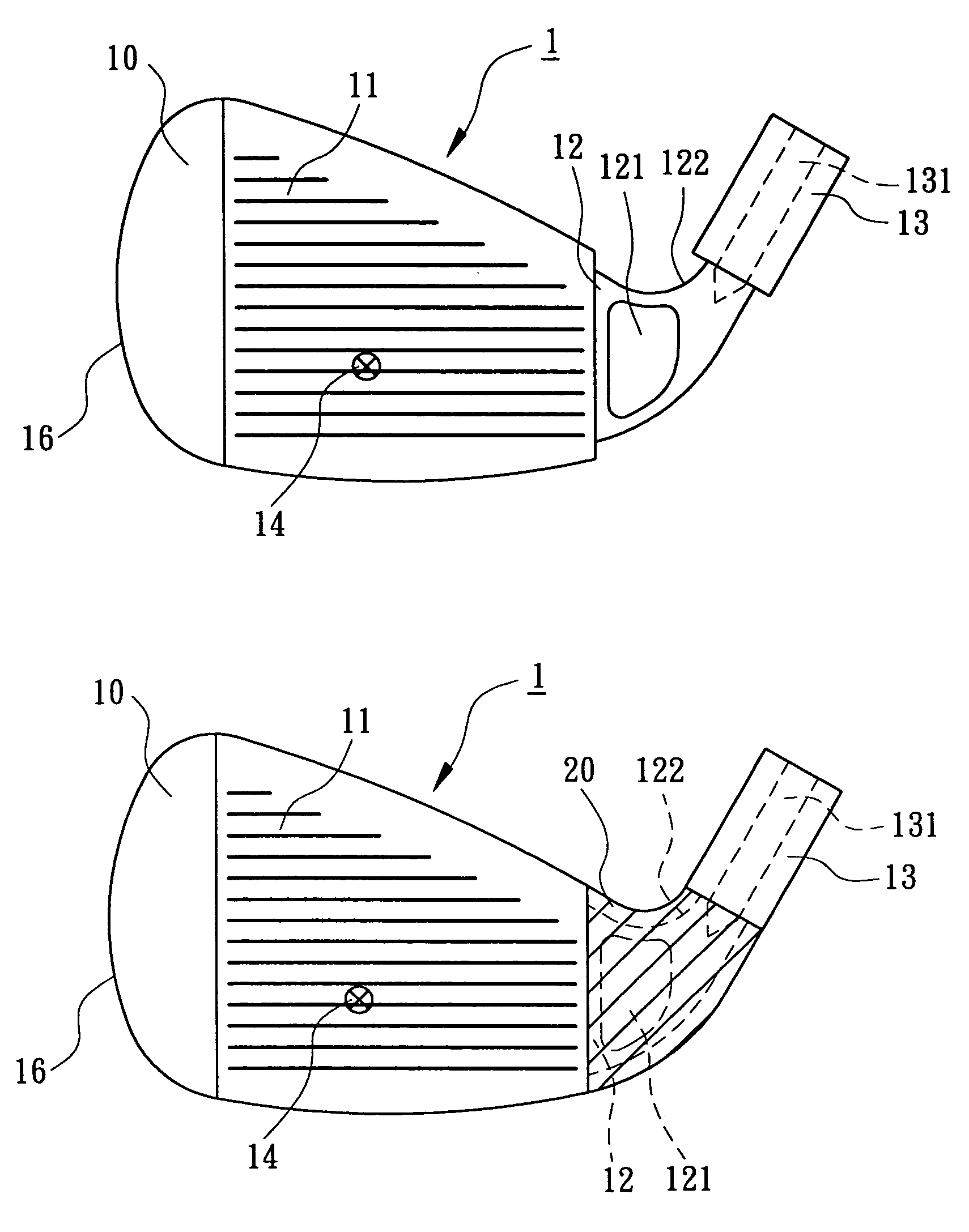
[0035]The heel 12 includes a hole 121 for reducing the weight of the heel 12. The hole 121 may be a through-hole or a blind hole having an opening in a rear side or a front side of the heel 12. The hole 121 uniformly decreases the weight of an upper portion of the heel 12 and the weight of a lower portion of the heel 12. Thus, the center of gravity 14 of the go...

second embodiment

[0037]FIGS. 5 and 6 illustrate the golf club head in accordance with the present invention. In this embodiment, the heel 12 further includes a reduced section 122. The reduced section 122 further reduces the weight of the heel 12. A wrapping layer 20 is made of light material. The wrapping layer 20 wraps the reduced section 122 and fills the hole 121. The light material is selected from a group consisting of carbon fiber, resin, rubber, high molecular polymeric material, and light alloy such as titanium alloy or aluminum alloy. The wrapping layer 20 wraps the reduced section 122 of the hosel 12 by heat pressing or injection molding. The wrapping material 20 allows further decrease in the weight of the heel 12 without adversely affecting the structural strength of the heel 12. Meanwhile, the wrapping layer 20 increases the damping value of the heel 12 of the golf club head 1 during striking. The shock generated as a result of striking a golf ball is absorbed by the wrapping layer 20 ...

fourth embodiment

[0039]FIG. 9 illustrates the golf club head in accordance with the present invention that is modified from the embodiment of FIGS. 7 and 8. In this embodiment, the reduced section 122 on the hosel 13 includes at least one protrusion 132 on an outer periphery thereof. The respective protrusion 132 includes an annular, circular, or elongated section. Thus, the bonding stability and reliability between the wrapping layer 20 and the reduced section 122 are improved by the respective protrusion 132.


PUM


Abstract

A golf club head includes a golf club head body having a toe and an engaging portion to which a striking plate is mounted, a hosel mounted to a side of the golf club head body, and a heel between the hosel and the engaging portion of the golf club head body. The heel includes a hole for reducing a weight of the heel, thereby shifting a center of gravity of the golf club head toward the toe of the golf club head body and increasing an inertial momentum of the golf club head.

Description

BACKGROUND OF THE INVENTION[0001]1. Field of the Invention[0002]The present invention relates to a golf club head. In particular, the present invention relates to a golf club head the weight of which is reduced for adjusting the center of gravity of the golf club head.[0003]2. Description of Related Art[0004]FIG. 1 of the drawings illustrates a typical golf club head 1 made of metal. The golf club head 1 includes a golf club head body 10, a striking plate 11, a heel 12, and a neck or hosel 13 to which a shaft (not shown) is mounted. The heel 12 connects the hosel 13 to the striking plate 11. The center of gravity 14 of the golf club head 1 is relatively close to the hosel side, as the hosel 13 has a considerable weight. Thus, the center of gravity 14 is not located in the sweet spot of the striking plate 11. As a result, the inertial moment of the golf club head 1 is reduced and the twist-resisting property of the golf club head 1 is adversely affected. Thus, the momentum imparted f...

Claims


Application Information

Patent Timeline
Patent Type & Authority Patents(United States)
IPC IPC(8): A63B53/04A63B53/02A63B59/00
CPCA63B53/047A63B2053/0491A63B2209/02A63B53/02A63B2053/0416A63B59/0088A63B59/0092A63B60/02A63B60/50A63B60/54A63B53/0416
Inventor CHEN, CHAN-TUNG
Owner FUSHENG PRECISION
Why Eureka
Try Eureka