Method of arranging optical pickup system and optical recording and/or reproducing apparatus having the arranged optical pickup system

a pickup system and optical pickup technology, applied in the direction of data recording, instruments, disposition/mounting of heads, etc., can solve the problems of difficult arrangement of optical pickup systems, inability and difficult to detect tracking error signals using dpd and three-beam methods

Inactive Publication Date: 2006-08-15
SAMSUNG ELECTRONICS CO LTD
View PDF13 Cites 2 Cited by
  • Summary
  • Abstract
  • Description
  • Claims
  • Application Information

AI Technical Summary

Problems solved by technology

Thus, where the photodetector 9 rotates at 45 degrees, it is not possible to detect a tracking error signal by the three-beam method since the sub-beams are not received onto the sub-photodetectors.
However, it is difficult to arrange the optical pickup system so as to have the optical path axis c be tilted relative to the tangential direction by 45 degrees due to the size of a motor mounted on the deck to rotate the optical disc 1.
The problem with the conventional method of arranging the optical pickup system (so that the optical path axis c1 is tilted relative to the axis of the tangential direction and the photodetector 9 is placed near the rotation center Mc of the motor) arises where a single pho...

Method used


Image

  • Method of arranging optical pickup system and optical recording and/or reproducing apparatus having the arranged optical pickup system
  • Method of arranging optical pickup system and optical recording and/or reproducing apparatus having the arranged optical pickup system
  • Method of arranging optical pickup system and optical recording and/or reproducing apparatus having the arranged optical pickup system

Examples


Embodiment Construction

[0072]Reference will now be made in detail to the present preferred embodiments of the present invention, examples of which are illustrated in the accompanying drawings, wherein like reference numerals refer to the like elements throughout. The embodiments are described below in order to explain the present invention by referring to the figures.

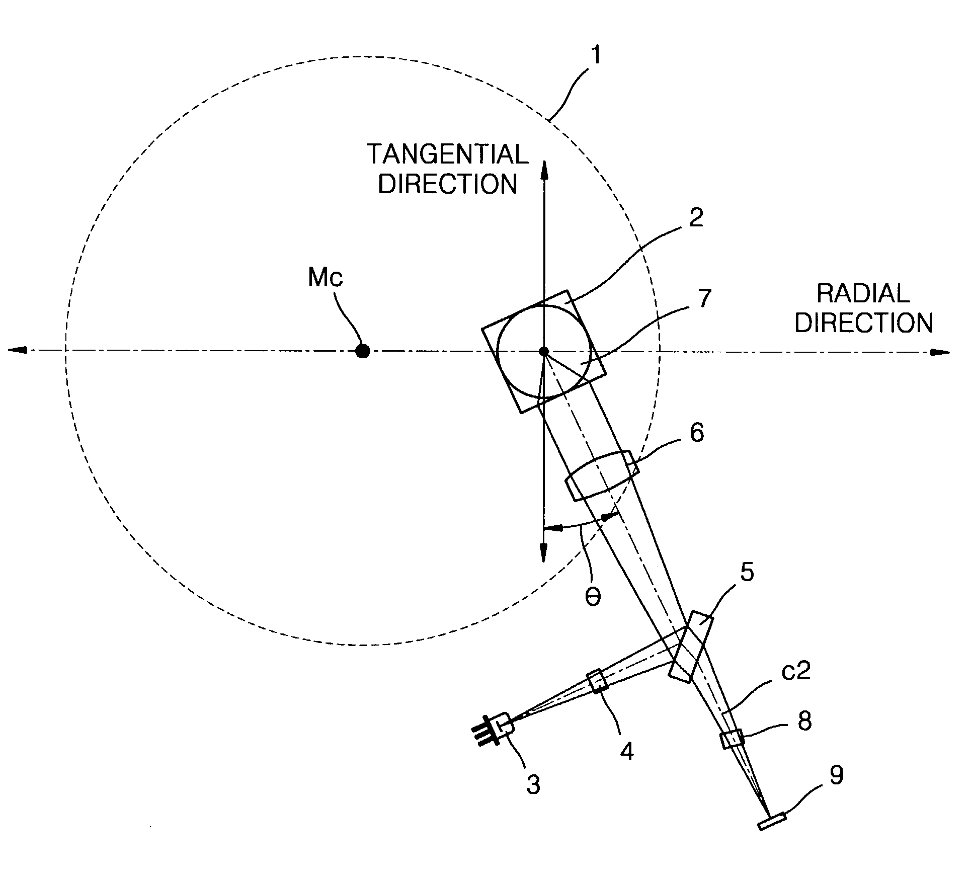
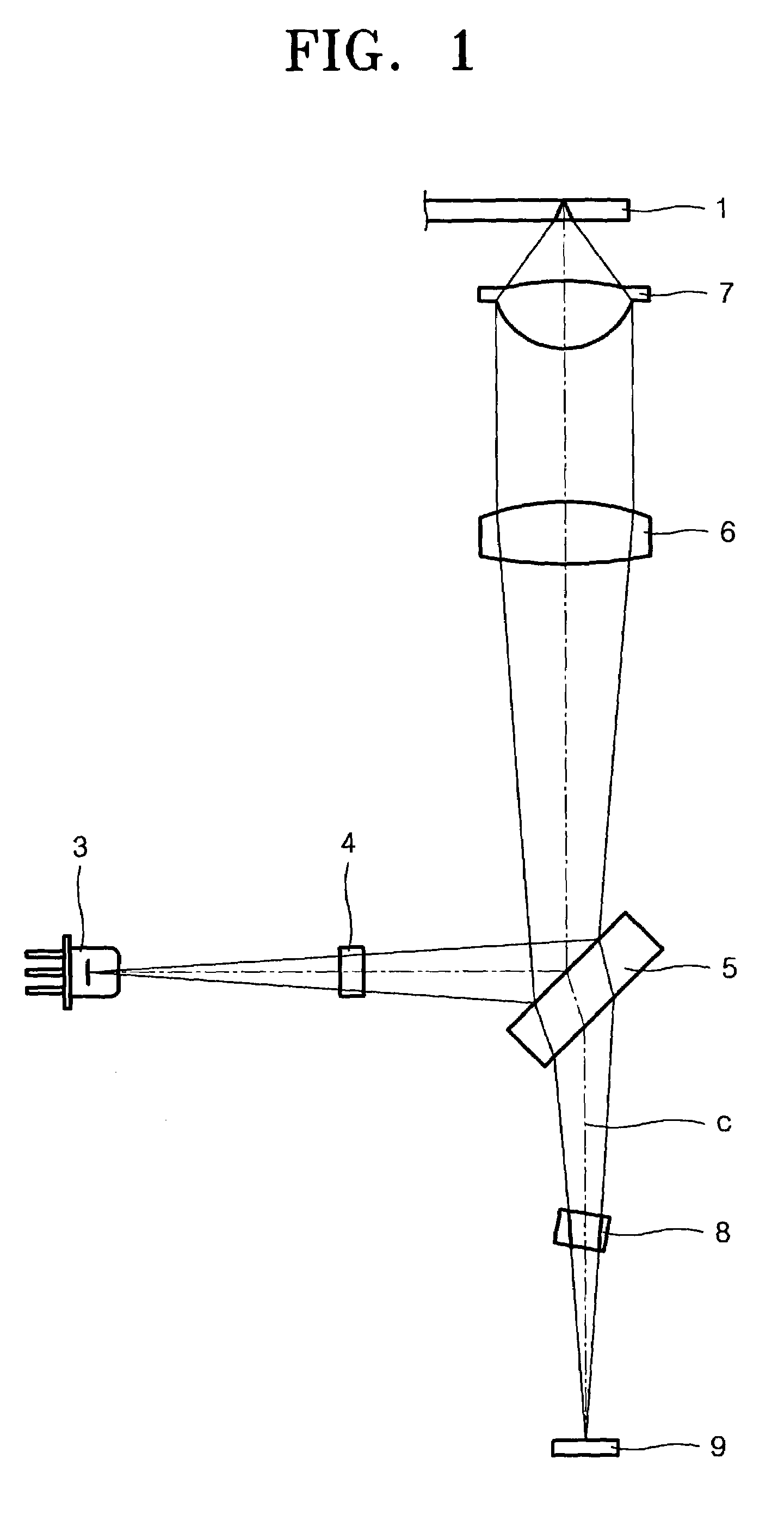
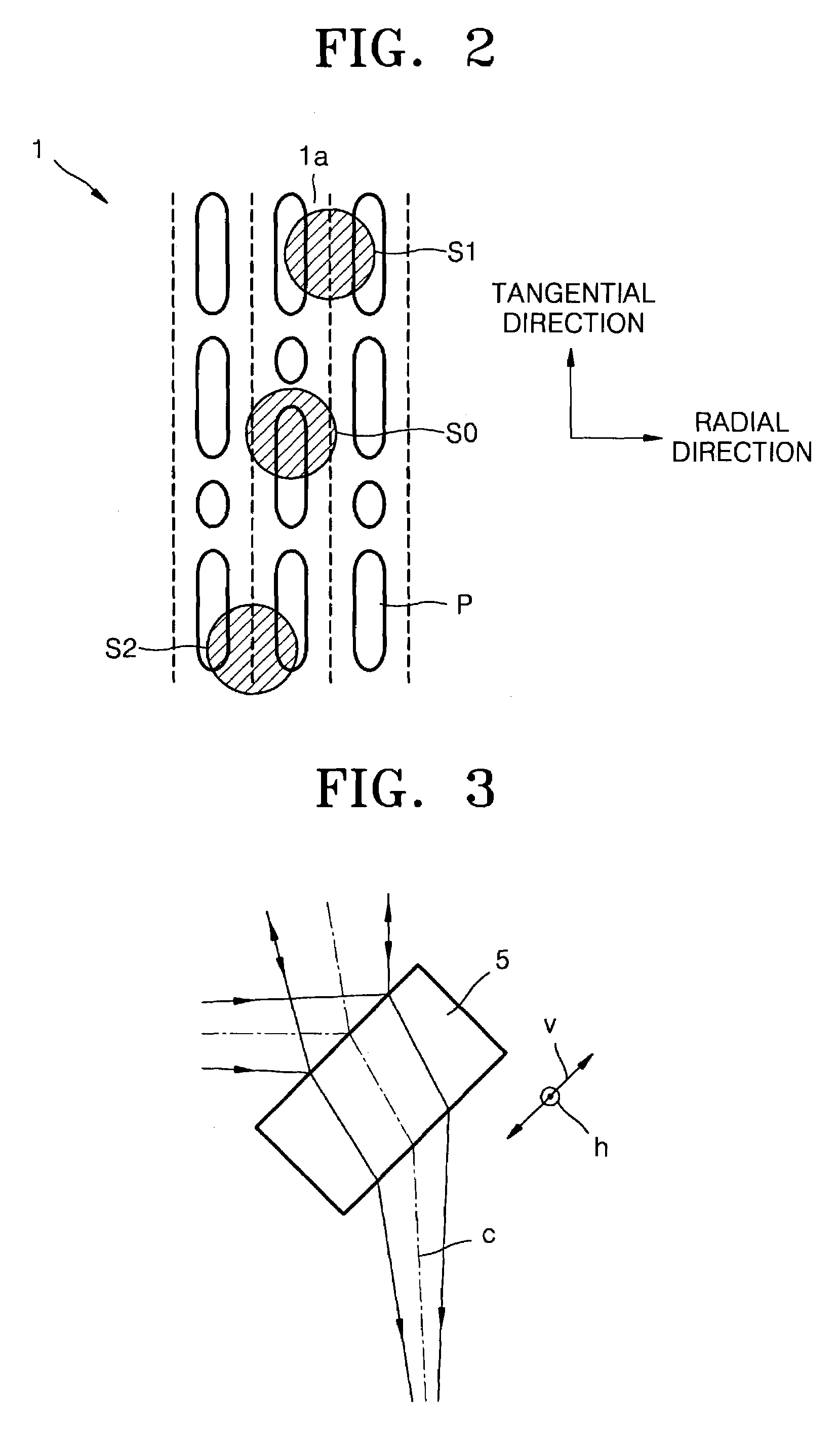
[0073]An optical pickup system arranged by an arrangement method according to the present invention includes a light source, a diffractive optical element, i.e., diffraction grating which diffracts a light beam incident from the light source and splits it into three or more beams, a plate-type beam splitter which converts a propagation path of the light beam, and a photodetector comprising at least one main photodetector having four or more sections, and a plurality of sub-photodetectors. The optical pickup system, constructed so that a reflecting mirror redirects the propagation path of the light beam emitted from the light source toward an ...


PUM


Abstract

A method of arranging an optical pickup system on a deck of an optical recording and/or reproducing apparatus, which enables detection of a tracking error signal using one photodetector based on a three-beam method and by a differential phase detection method. The optical pickup system includes a light source, a diffractive optical element which diffracts a light beam incident from the light source and splits the same into at least three beams, a plate-type beam splitter which changes a propagation path of the light beam, and a photodetector including at least one main photodetector having at least four sections and a plurality of sub-photodetectors. The optical pickup system is constructed so as to have a reflecting mirror redirect the propagation path of the light beam emitted from the light source toward a recording medium. The method of arranging the optical pickup includes, where the propagation path of the light beam transmitted through the plate-type beam splitter to the photodetector is an optical path axis, arranging the optical pickup system so as to have the optical path axis tilted with respect to an axis in a tangential direction of the recording medium and have the photodetector placed away from a rotation center of a motor that rotates the recording medium, and selectively optimizing the arrangement of the photodetector to detect a tracking error signal by the differential phase detection method.

Description

CROSS-REFERENCE TO RELATED APPLICATIONS[0001]This application claims the benefit of Korean Patent Application Nos. 2002-33398, filed Jun. 14, 2002 and 2003-25530, filed Apr. 22, 2003, the disclosures of which are incorporated herein by reference.BACKGROUND OF THE INVENTION[0002]1. Field of the Invention[0003]The present invention relates to a method of arranging an optical pickup system and an optical recording and / or reproducing apparatus having the arranged optical pickup system.[0004]2. Description of the Related Art[0005]FIG. 1 shows an example of the optical configuration of an optical pickup. Referring to FIG. 1, the optical pickup includes a light source 3 which emits light of a predetermined wavelength, a plate-type beam splitter 5 which changes a propagation path of a light beam emitted by the light source 3, an objective lens 7 which focuses an incident light beam to a spot on a recording surface of an optical disc 1, and a photodetector 9 which detects an information sign...

Claims


Application Information

Patent Timeline
IPC IPC(8): G11B7/00G11B7/09G11B7/135G11B7/095G11B7/13G11B7/131
CPCG11B7/0903G11B7/131G11B7/0906G11B2007/0006
Inventor KIM, BONG-GIPARK, CHUN-SEONGPARK, SOO-HANLEE, MOON-WHANLEE, HYO-CHANKIM, JONG-UKPARK, SEONG-SUHEOR, TAE-YOUNNAM, DO-HOAN
Owner SAMSUNG ELECTRONICS CO LTD
Why Eureka
Try Eureka