Drive circuit for an injector arrangement and a diagnostic method

a technology of injector arrangement and drive circuit, which is applied in the direction of machines/engines, electrical control, instruments, etc., can solve the problems of catastrophic engine failure and failure of drive circui

Active Publication Date: 2007-10-04
DELPHI TECH IP LTD
View PDF9 Cites 66 Cited by
  • Summary
  • Abstract
  • Description
  • Claims
  • Application Information

AI Technical Summary

Benefits of technology

[0024]According to a second aspect of the invention there is provided a drive circuit for an injector arrangement comprising a fuel injector, the drive circuit comprising diagnostic means in a connection of the drive circuit to a ground potential, the diagnostic means being operable: a) to sense a detected current; and b) to provide a signal on detection of a fault, wherein the signal is provided when the detected current i

Problems solved by technology

Like any circuit, faults may occur in a drive circuit.
In safety critical systems, such as diesel engine fuel injection systems, a fault in

Method used


Image

  • Drive circuit for an injector arrangement and a diagnostic method
  • Drive circuit for an injector arrangement and a diagnostic method
  • Drive circuit for an injector arrangement and a diagnostic method

Examples


first embodiment

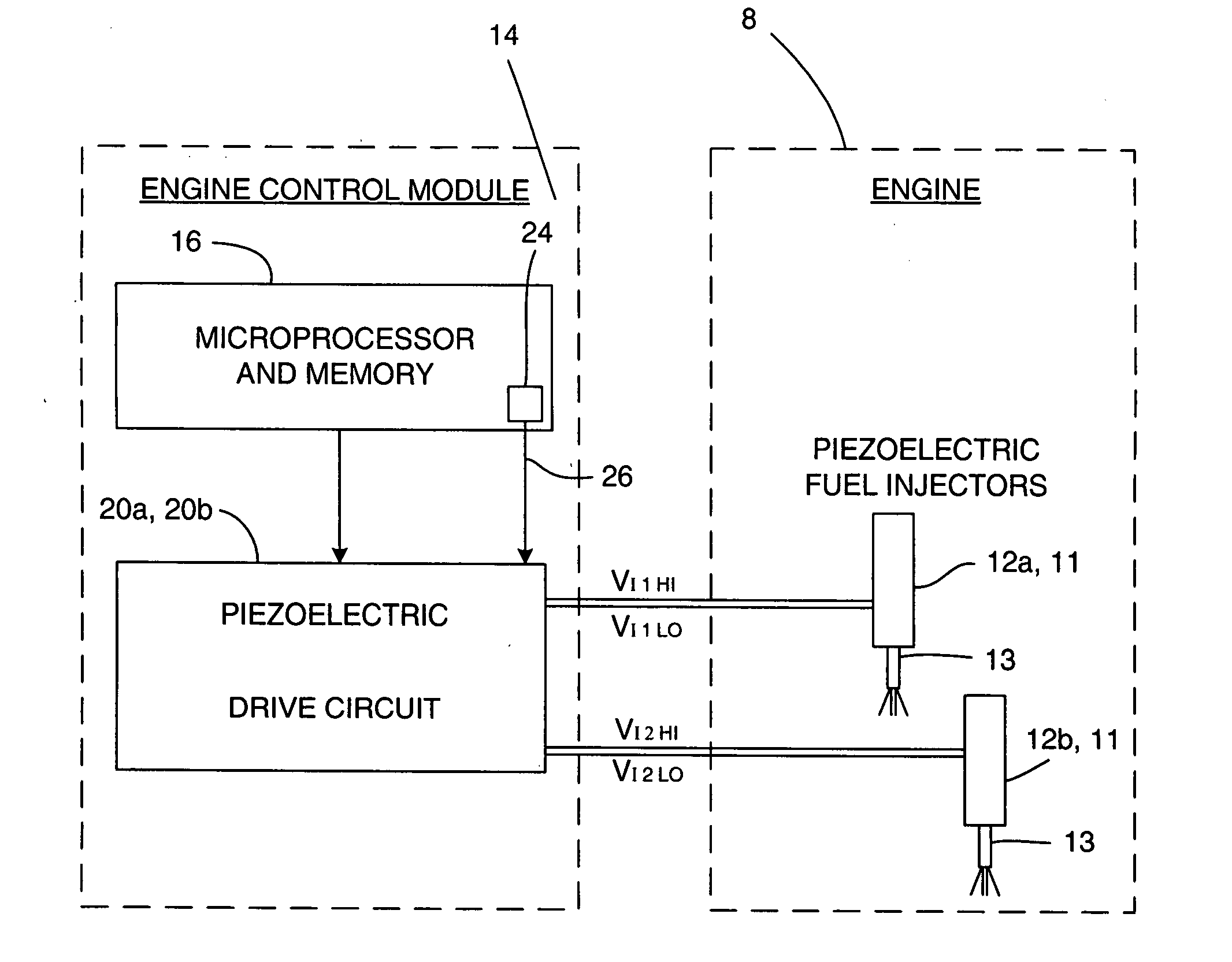
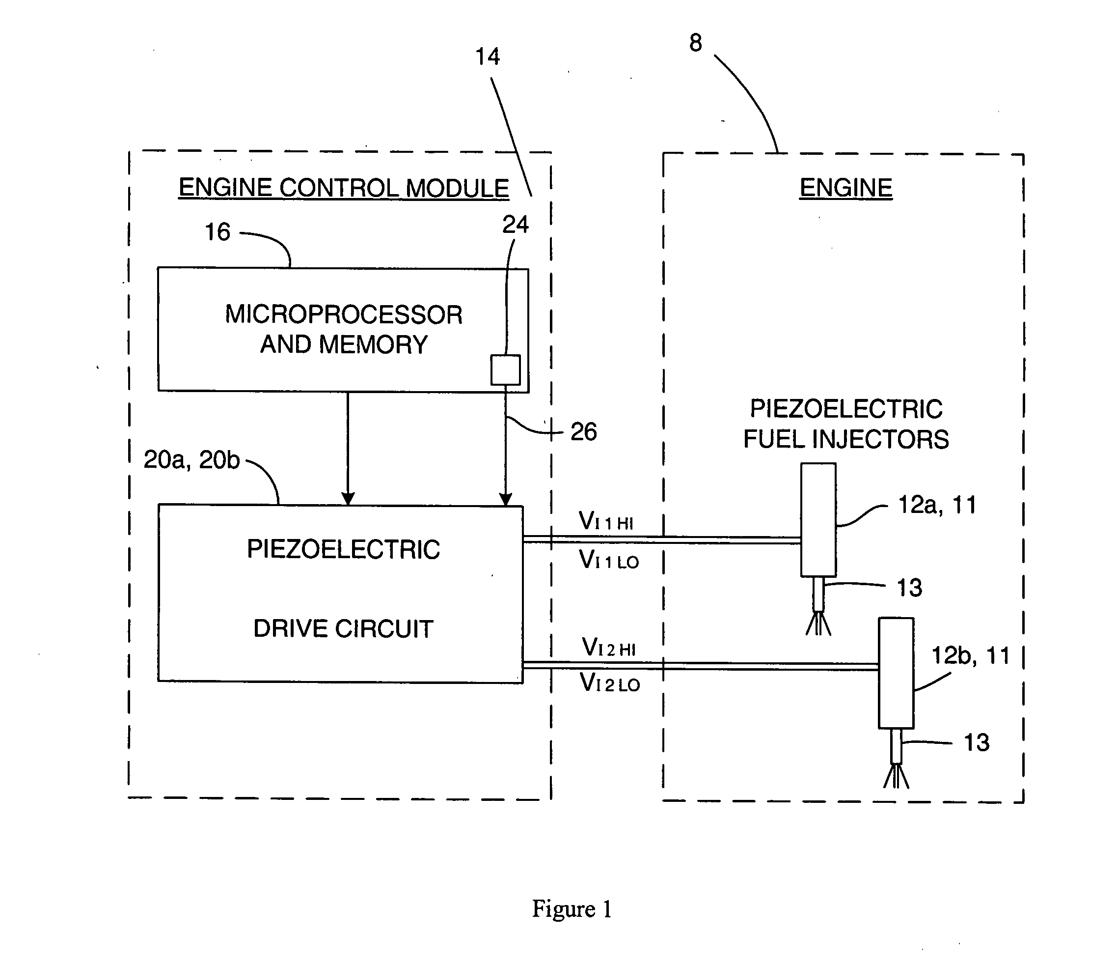
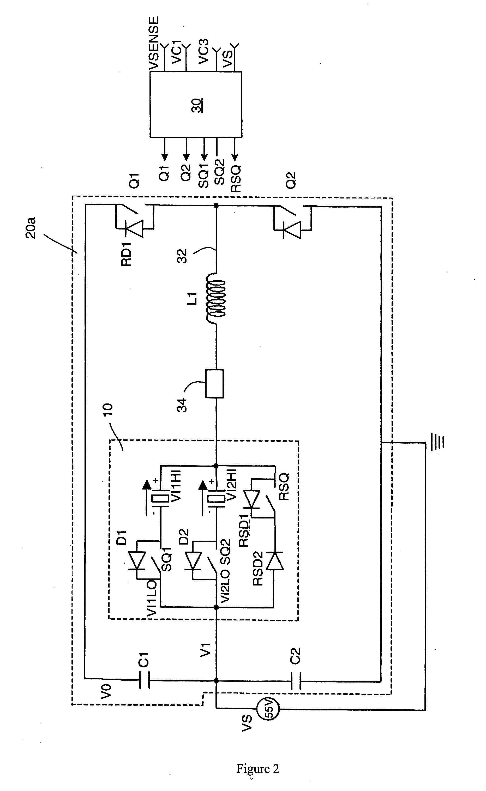
[0119]the diagnostic tool is a resistive bias network comprising a first resistor RH and a second resistor RL. The first resistor RH is connected between the first voltage rail V0 and the high side of the fuel injectors 12a, 12b at a bias point PB that is connected to the inductor L1. The second resistor RL is also connected to the high side of the fuel injectors 12a, 12b, at the bias point PB, and to the ground potential VGND. The first and second resistors RL and RH each have a known resistance of a high order of magnitude. A volt sensor 25 is connected across the second resistor RL and provides an output to the microprocessor 16. The microprocessor 16 is arranged to operate the volt sensor 25 and receives signals from the volt sensor 25 indicative of a bias voltage across the second resistor RL.

second embodiment

[0120]In the diagnostic tool, referred to as a fault trip circuit, a fault trip resistor RF, in the connection of the drive circuit 20a to the ground potential VGND. A current sensor 27 is connected in series with the fault trip resistor RF in order to sense the current that passes through the fault trip resistor RF. The fault trip resistor RF is of very low resistance with an order of magnitude of milliohms. The microprocessor 16 is arranged to transmit control signals to the current sensor 27 and receives signals from the current sensor 27 indicative of the current flow through the fault trip resistor RF.

[0121]Note that, because the fault trip resistor RF is in series with the ground potential VGND that is connected to all of the banks in an injector arrangement, only one fault trip resistor RF is required. Thus, in using the fault trip circuit, if a failure of the drive circuit 20a or the bank 10 is detected, it will only be possible in some circumstances to determine that there ...


PUM


Abstract

The invention relates to a drive circuit for an injector arrangement comprising a fuel injector, and method of detecting faults in the drive circuit. The drive circuit comprises diagnostic means (RH, RL) that is operable to sense a measured voltage (VBIAS) between the injector and a known voltage level (VBAT, VGND). The measured voltage (VBIAS) is biased with respect to the known voltage (VBAT, VGND) to a predicted voltage (VPinjN, VBcalc) unless the drive circuit has a fault. A fault signal is provided on sensing of a measured voltage (VBIAS) that differs from the predicted voltage (VPinjN, VBcalc). The drive circuit may additionally, or alternatively, comprise diagnostic means (RF). The diagnostic means (RF) is operable to sense a detected current (Idect) and to provide a fault signal on detection of a fault, when the detected current (Idect) is at variance from a threshold current (Itrip).

Description

TECHNICAL FIELD[0001]The present invention relates to a drive circuit for an injector arrangement having a diagnostic means for detecting a fault, and a diagnostic method for the drive circuit of an injector arrangement. The drive circuit is especially, although not exclusively, for an injector arrangement in an internal combustion engine, the injector arrangement including an injector of the type having a piezoelectric actuator for controlling injector valve needle movement.BACKGROUND ART[0002]Automotive vehicle engines are generally equipped with fuel injectors for injecting fuel (e.g., gasoline or diesel fuel) into the individual cylinders or intake manifold of the engine. The engine fuel injectors are coupled to a fuel rail which contains high pressure fuel that is delivered by way of a fuel delivery system. In diesel engines, conventional fuel injectors typically employ a valve that is actuated to open and to close in order to control the amount of fluid fuel metered from the f...

Claims


Application Information

Patent Timeline
IPC IPC(8): F02M51/00G06F19/00H01H47/00H01L41/00
CPCF02D41/062F02D41/2096F02D41/221F02D2041/2003F02D2041/2093F02D2041/2051F02D2041/2058F02D2041/2072F02D2041/2089F02D2041/2006
Inventor PERRYMAN, LOUISABAKER, NIGEL P.MARTIN, STEVENSYKES, MARTIN A. P.
Owner DELPHI TECH IP LTD
Why Eureka
Try Eureka