Display device having optical sensors

a technology of optical sensors and display devices, applied in the field of display devices, can solve the problems of difficult to distinguish between shadow images and background, touch positions may not be able to be detected properly, etc., and achieve the effect of reducing the luminance of backlight, high accuracy, and high accuracy

Inactive Publication Date: 2011-01-13
SHARP KK
View PDF8 Cites 71 Cited by
  • Summary
  • Abstract
  • Description
  • Claims
  • Application Information

AI Technical Summary

Benefits of technology

[0022]According to the first aspect of the present invention, since the filter portions that allow infrared light to pass therethrough and cut off visible light are provided in the respective paths of light entering the optical sensors, an image obtained by the optical sensors is not influenced by visible light included in outside light or backlight light, enabling to detect reflected light of infrared light emitted from the backlight by the optical sensors. Accordingly, infrared light reflected off a matter present in the vicinity of the front surface of the display panel is detected and a touch position can be detected with high accuracy, based on an image that is not influenced by visible light included in large amount in outside light or other light sources (backlight). In addition, in the display panel that allows infrared light to pass therethrough more easily than visible light, by increasing the light reception sensitivity of the display panel, a touch position can be detected with high accuracy. In addition, even if display data is changed, the transmittance of infrared light does not change and thus a touch position can be detected irrespective of display data. Furthermore, by reducing the luminance of the backlight by an amount corresponding to the increase in light reception sensitivity, the power consumption of the backlight can be reduced.
[0023]According to the second aspect of the present invention, when the pixel circuits and the optical sensors are formed of polysilicon having the light reception sensitivity of infrared light, infrared light emitted from the backlight is detected by the optical sensors, enabling to detect a touch position based on a result of the detection.
[0024]According to the third or fourth aspect of the present invention, a display device that can detect a touch position with high accuracy, irrespective of display data can be configured using a backlight that emits infrared light having a peak wavelength in the absorption spectrum of the atmosphere (more preferably, in a range of 850 nm to 960 nm). In addition, by providing filters whose pass band includes the wavelength range of light emitted from the backlight, in the respective paths of light entering the optical sensors, the influence of sunlight exerted on an image obtained by the optical sensors is reduced, enabling to detect a touch position with higher accuracy.
[0025]According to the fifth aspect of the present invention, by adding a second luminous element to a backlight that emits visible light, a backlight that emits both visible light and infrared light can be configured using a conventional backlight as it is.
[0026]According to the sixth aspect of the present invention, by arranging a luminous element that emits visible light and a luminous element that emits infrared light on the same substrate or enclosing such luminous elements in the same package, a small-size backlight that emits both visible light and infrared light can be configured.
[0027]According to the seventh aspect of the present invention, by providing a backlight that emits only infrared light, a reflective-type display device can be configured that can detect a touch position with high accuracy, irrespective of display data.

Problems solved by technology

In the method of detecting a shadow image, when the illumination of outside light is low (the surroundings are dark), it becomes difficult to distinguish between a shadow image and a background in an image obtained by the optical sensors and accordingly a touch position may not be able to be detected properly.

Method used


Image

  • Display device having optical sensors
  • Display device having optical sensors
  • Display device having optical sensors

Examples


first embodiment

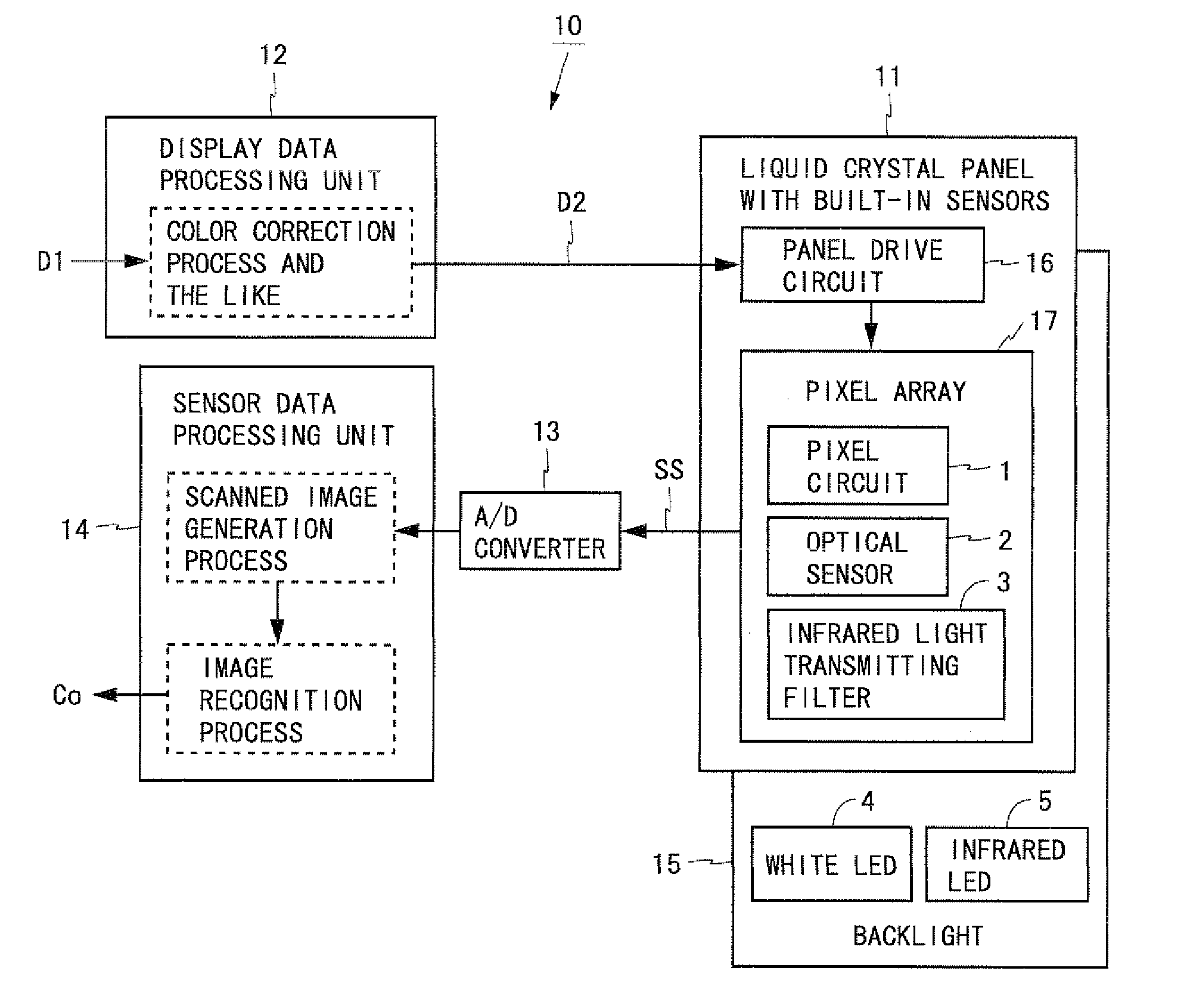
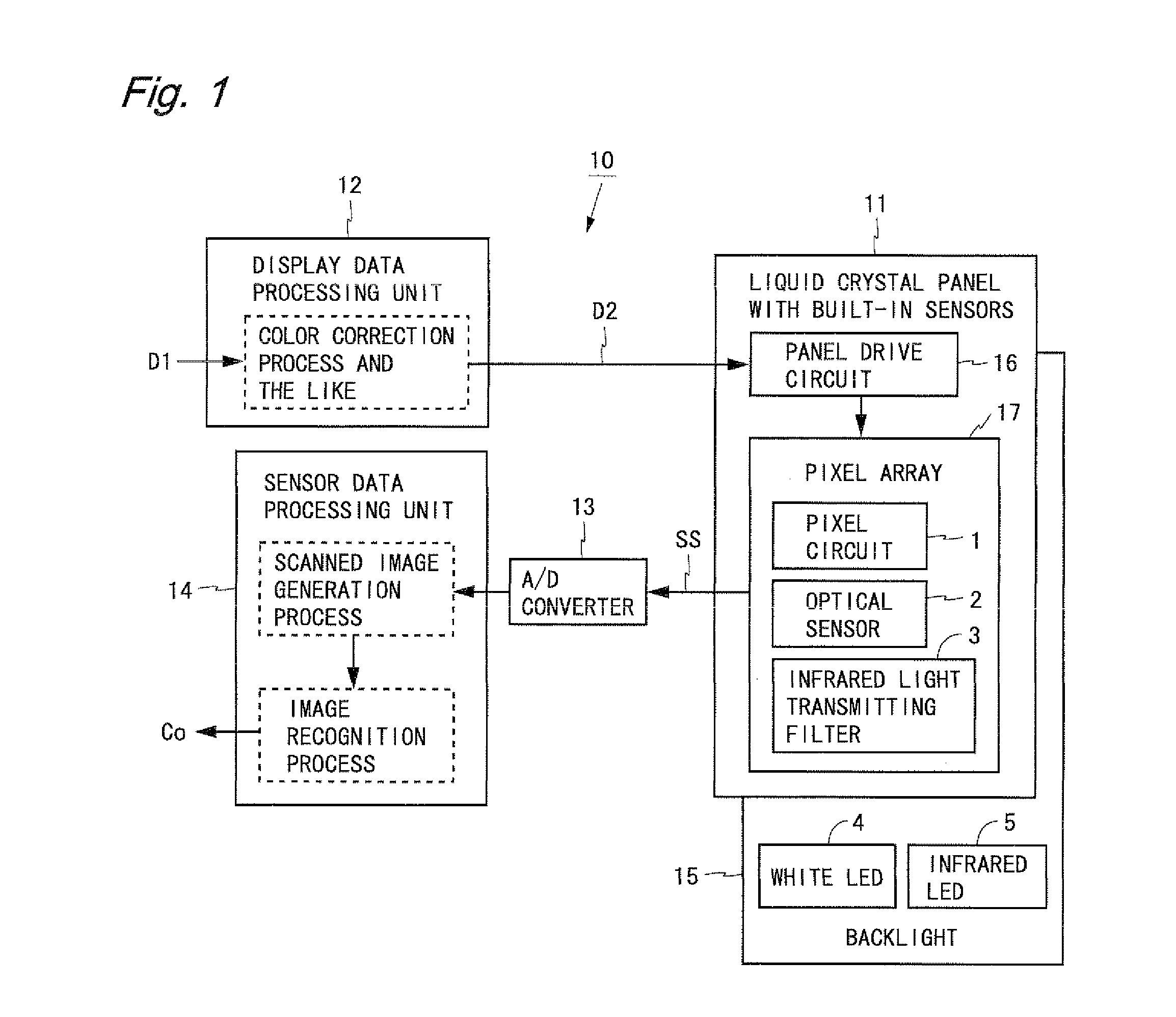
[0081]FIG. 1 is a block diagram showing a configuration of a liquid crystal display device according to a first embodiment of the present invention. A liquid crystal display device 10 shown in FIG. 1 includes a liquid crystal panel with built-in sensors 11, a display data processing unit 12, an A / D converter 13, a sensor data processing unit 14, and a backlight 15. The liquid crystal panel with built-in sensors 11 (hereinafter, referred to as the liquid crystal panel 11) includes a panel drive circuit 16 and a pixel array 17. The pixel array 17 includes a plurality of pixel circuits 1 and a plurality of optical sensors 2 which are arranged two-dimensionally. Infrared light transmitting filters 3 that allow infrared light to pass therethrough and cut off visible light are provided in respective paths of light entering the optical sensors 2.

[0082]Display data D1 is inputted to the liquid crystal display device 10 from an external source. The display data processing unit 12 performs, i...

second embodiment

[0119]FIG. 16 is a block diagram showing a configuration of a liquid crystal display device according to a second embodiment of the present invention. A liquid crystal display device 18 shown in FIG. 16 is such that in the liquid crystal display device 10 according to the first embodiment the backlight 15 is replaced by a backlight 19. The backlight 19 includes infrared LEDs 5 but does not include any luminous element that emits visible light. In other words, the backlight 19 includes, as a light source, only the infrared LEDs 5 that emit infrared light. Except for the above-described point, the configuration of the liquid crystal display device 18 according to the present embodiment is the same as that of the liquid crystal display device 10 according to the first embodiment.

[0120]By thus providing the backlight 19 that emits only infrared light, a reflective-type liquid crystal display device that can detect a touch position with high accuracy, irrespective of display data can be ...

third embodiment

[0121]A liquid crystal display device according to a third embodiment of the present invention has the same configuration as the liquid crystal display device 10 according to the first embodiment (see FIG. 1). In the present embodiment, the characteristics of infrared light transmitting filters 3 and a liquid crystal display device including a filter other than the infrared light transmitting filters 3 will be described. In the following, examples of a liquid crystal panel with built-in sensors (hereinafter, referred to as the liquid crystal panel) which is included in the liquid crystal display device according to the present embodiment will be described.

[0122]FIG. 17 is a diagram showing a cross section of a first example of the liquid crystal panel. In a liquid crystal panel 81 shown in FIG. 17, an infrared light transmitting filter 3 is provided above a photodiode 24 included in an optical sensor 2. The infrared light transmitting filter 3 has a pass band suitable for infrared l...


PUM


Abstract

A liquid crystal panel with built-in sensors 11 includes, in a pixel array 17, a plurality of pixel circuits 1 and a plurality of optical sensors 2 which are arranged two-dimensionally. Infrared light transmitting filters 3 that allow infrared light to pass therethrough and cut off visible light are provided in respective paths of light entering the optical sensors 2. A backlight 15 including white LEDs 4 and infrared LEDs 5 is provided on a back surface of the liquid crystal panel 11. With this, reflected light of backlight light including infrared light is detected by the optical sensors 2 without receiving the influence of visible light, and thus a touch position is detected with high accuracy, irrespective of display data.

Description

TECHNICAL FIELD[0001]The present invention relates to a display device and more particularly to a display device having a plurality of optical sensors provided in a display panel.BACKGROUND ART[0002]In recent years, electronic devices that can be operated by touching a screen with a finger, a pen, etc., have proliferated. In addition, for a method of detecting a touch position on a display screen, a method is known in which a plurality of optical sensors are provided in a display panel and a shadow image which is created when a finger or the like approaches the screen is detected using the optical sensors. In the method of detecting a shadow image, when the illumination of outside light is low (the surroundings are dark), it becomes difficult to distinguish between a shadow image and a background in an image obtained by the optical sensors and accordingly a touch position may not be able to be detected properly. In view of this, for display devices including a backlight, a method is...

Claims


Application Information

Patent Timeline
Patent Type & Authority Applications(United States)
IPC IPC(8): G09G5/00
CPCG02F1/13338G02F2203/11G02F2001/13312G02F1/133509G02F1/13312
Inventor FUJIOKA, AKIZUMIGOTOH, TOSHIMITSUKUBOTA, AKINORIUEHATA, MASAKI
Owner SHARP KK
Why Eureka
Try Eureka