
Multi-layered electrochemical microfluidic sensor comprising reagent on porous layer

a microfluidic sensor and electrochemical technology, applied in biochemistry equipment, biochemistry equipment and processes, instruments, etc., can solve the problems of inability to quantitatively measure, color may slightly change, and difficult interpretation of band intensity and antigen concentration correlation

Inactive Publication Date: 2006-06-29
DIAGNOSWISS
View PDF29 Cites 67 Cited by
  • Summary
  • Abstract
  • Description
  • Claims
  • Application Information

AI Technical Summary

Benefits of technology

"The present invention provides a microfluidic assay apparatus and a method for performing a microfluidic assay. The apparatus includes a multi-layer body composed of at least three layers: a polymer layer with at least one fluidic connection, a non-porous layer for waterproof sealing of the microstructure, and a porous layer in contact with the microstructure. The apparatus can detect analytes in a test solution using a microelectrode integrated in the polymer layer and electrically conductive tracks. The invention also provides a method for making the apparatus and a method for performing the microfluidic assay. The technical effects of the invention include improved accuracy and sensitivity of the microfluidic assay, simplified operation, and reduced cost."

Problems solved by technology

Nevertheless, depending on the experimenter or on the daylight, the perception of the color may slightly change, and the measurement cannot be taken as quantitative as the one of the pH meter with pH electrode.
This method is mainly used for qualitative assays because the interpretation of the band intensity and its correlation with the antigen concentration is very difficult.
In most analytical systems, the detection is achieved directly within the porous layer which renders a washing step difficult or impossible prior to the detection.
The performance of this system is satisfactory but the delivery of different successive reagents implies quite a large infrastructure around the microsystem, as well as cumbersome manipulations which take time and reduce the assay reproducibility.

Method used


Image

  • Multi-layered electrochemical microfluidic sensor comprising reagent on porous layer
  • Multi-layered electrochemical microfluidic sensor comprising reagent on porous layer
  • Multi-layered electrochemical microfluidic sensor comprising reagent on porous layer

Examples


example 1

pH Measurement

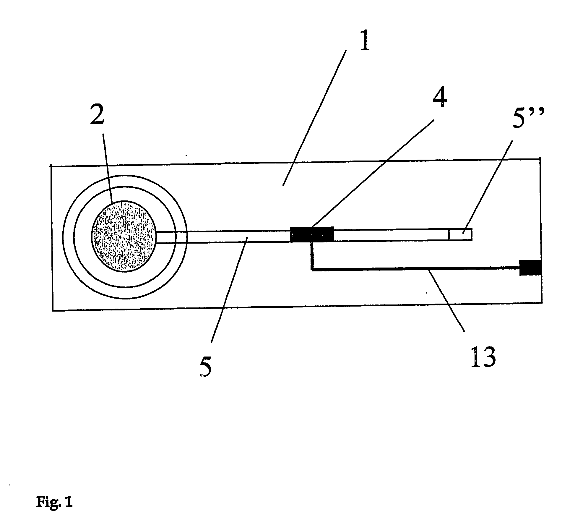
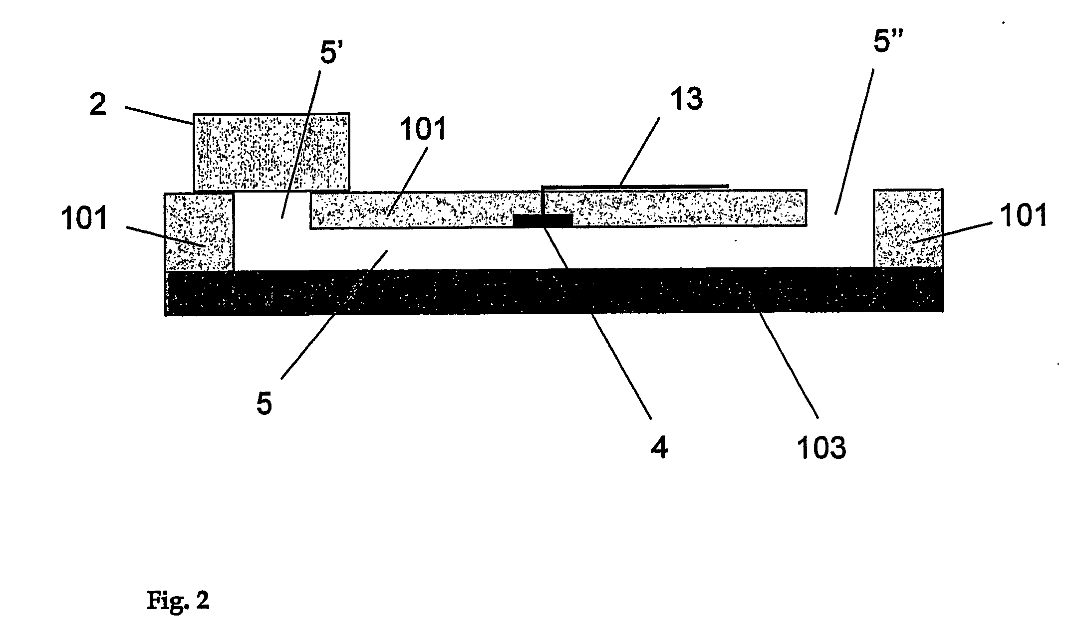
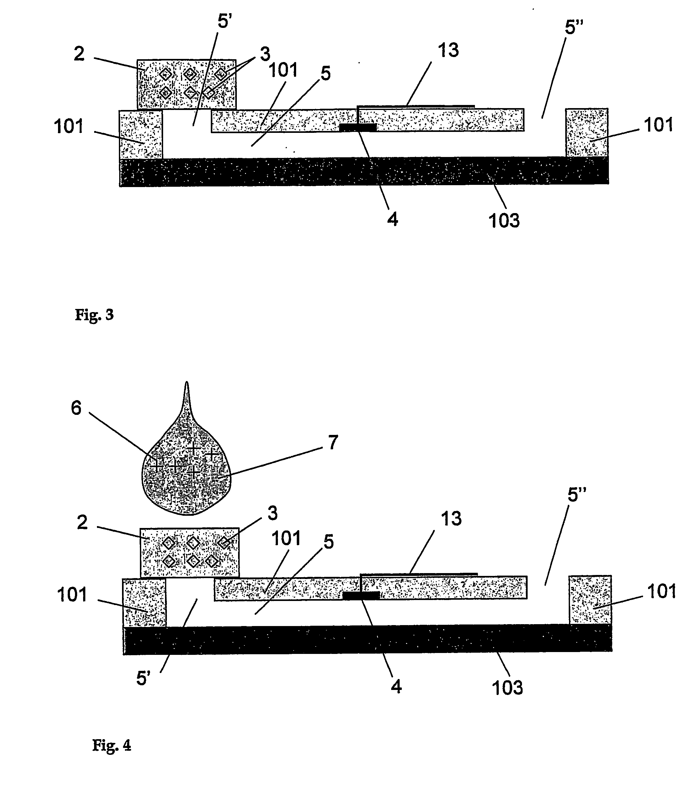
[0072] In a first embodiment, the analyte to be tested in different test solutions is the proton concentration, namely the pH of the solution. In the apparatus shown in FIGS. 1 to 6, aminophenol (1 mM) is used as a reagent dried in the porous layer which is a cellulose membrane. This membrane is placed at the entrance of a microstructure serving as a fluidic connection. This microstructure is a 60 micrometer deep microchannel made of a 75 micrometer polyimide layer covered by a ˜40 micrometer thick polyethylene / polyethyleneterephthalate layer. The detection portion consists in an array of two microelectrodes that have an approximate diameter of 50 micrometers and that are made of copper coated by electroplated gold. These microelectrodes are part of the microchannel wall and exhibit a recess of about 15 micrometers. These microelectrodes are connected to an external potentiostat by way of gold / copper electrical tracks that are connected to a portable potentiostat (Pal...

example 2

Enzymatic Reaction (Case I: Substrate or Mediator in the Porous Layer)

[0076] In a further embodiment, the reagent placed in the porous layer is hydroquinone (HQ) which acts as a mediator in the enzymatic detection of the enzyme horseradish peroxidase (HRP) in the presence of H2O2 following the mechanism already described elsewhere Rossier et al. Lab-on-a-Chip, 2001,1,153-157).

[0077] The following conditions are shown in FIG. 23: [0078] A) cyclic voltammogram of the mixture of 10 mM hydroquinone and 10 mM H2O2 in phosphate buffer saline solution PBS pH 7.2; [0079] B) cyclic voltammogram of the mixture of 10 mM hydroquinone and 10 mM H2O2 in phosphate buffer saline solution PBS pH 7.2 with HRP added to the solution; [0080] C) cyclic voltammogram obtained with the apparatus shown in FIGS. 1 to 6 where hydroquinone is immobilized in the membrane as reagent and where H2O2 and horseradish peroxidase (HRP) are used as test solution in phosphate buffer saline solution PBS pH 7.2; [0081] D...

example 3

Enzymatic Reaction (Case II: Enzyme in the Porous Layer)

[0085] In another embodiment, the enzyme is immobilized in the membrane so as to be dissolved by the test solution, here HQ / H2O2. The reaction occurs and the solution with the enzyme is brought towards the detection portion as shown in FIG. 23 line E where HRP was first dried in the membrane. In order to favor the dissolution and displacement of the enzyme towards the detection portion, the membrane can be precoated with bovine serum albumin (BSA) in order to avoid significant non specific adsorption of the enzyme in the membrane.


PUM

PropertyMeasurementUnit
diameteraaaaaaaaaa
pHaaaaaaaaaa
microstructureaaaaaaaaaa

Abstract

The present invention relates to a microfluidic electrochemical sensor apparatus and a method for conducting analytical tests with said apparatus for multi-reactant assays. The apparatus of this invention is a multi-layer body made of at least three layers, the first one being a polymer layer (1) comprising a microstructure (5) with at least one integrated microelectrode (4) and conductive tracks (13) for connection to an external electrochemical unit, the second one being a non-porous material serving to cover said microstructure so as to enable microfluidic manipulations and the third one being a porous layer (2) such as a membrane or a glass frit, said porous layer comprising at least one reagent (3) to be solubilized upon contact with a test solution (7) and reacting with an analyte (6) present in said solution to form a product that is transported along said microstructure so as to enable electrochemical detection of said analyte. The invention notably enables the performance of multi-reactant assays in a reduced number of steps.

Description

BACKGROUND TO THE INVENTION [0001] Many qualitative or semi-quantitative chemical or biochemical assays are performed with a solid support, which is often a porous layer, where a reagent is stored dried and reacts when the solution to be tested wets this solid support or when the solid support is immersed or placed in contact with said test solution Well-known examples of such assay apparatuses are the strips used to determine the pH of a solution or those used to diagnose the presence of a given analyte by immunological or enzymatic assays (as e.g. in pregnancy tests or, respectively, glucose monitoring). [0002] In the first case, the pH is measured by immersion of a strip in an aqueous solution, where some pH indicators are dissolved and change their color depending on the pH of the solution. This system is very convenient because it rapidly gives a first estimation of the actual pH of the solution. Nevertheless, depending on the experimenter or on the daylight, the perception of ...

Claims


Application Information

Patent Timeline
Patent Type & Authority Applications(United States)
IPC IPC(8): C12Q1/68C12M1/34G01N33/558B01L3/00G01N27/30G01N27/403G01N33/487
CPCB01L3/502707B01L2300/0645B01L2300/0825B01L2300/0887B01L2400/0406B01L2400/0415B01L2400/0487G01N27/333
Inventor ROSSIER, JOEL STEPHANEREYMOND, FREDERICMORIER, PATRICK
Owner DIAGNOSWISS
Learn More