System and method for detecting variation of heart rate of a user

a technology of user heart rate and detection method, which is applied in the field of physiological signal detection of cardiovascular systems, can solve problems such as suspicious data of arrhythmias, and achieve the effect of enabling the detection of user heart rate variation and being more accura

Inactive Publication Date: 2017-01-19
KONINKLJIJKE PHILIPS NV
View PDF3 Cites 70 Cited by
  • Summary
  • Abstract
  • Description
  • Claims
  • Application Information

AI Technical Summary

Benefits of technology

[0010]It is an object of the present invention to provide a system and a method which enable detection of variation of heart rate of a user, which is more accurate, especially when there is doubt on the normalcy of the heart rate, while being user-friendly.

Problems solved by technology

Furthermore, during the first stage, the optical measurement may result in arrhythmia-suspicious data, which in reality are caused by insufficient measurement accuracy.

Method used


Image

  • System and method for detecting variation of heart rate of a user
  • System and method for detecting variation of heart rate of a user
  • System and method for detecting variation of heart rate of a user

Examples


first embodiment

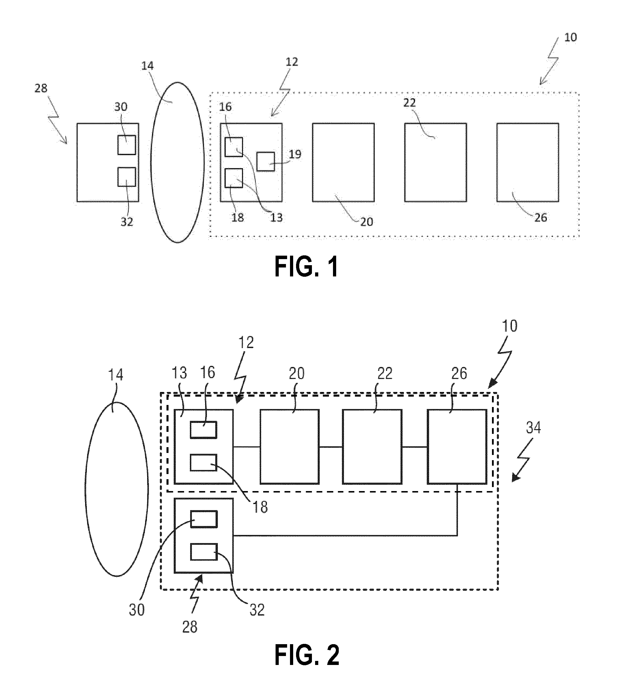
[0036]With reference to FIG. 1 a schematic block diagram of a device 10 for detecting heart rate variation in accordance with a first embodiment is shown. The device 10 comprises an optical sensing unit 12 such as an optical sensor for measuring a heartbeat-related optical signal of a living being 14 over time, the living being the user of the device 10. Such optical sensor units are known in the art. A possible optical sensor will be briefly described now. Note that other optical sensors are also possible in relation to the invention. As shown in FIG. 1, the optical sensing unit 12 may comprise an emitter 16 (for example an LED) for emitting light to the living being 14 and a photo detector 18 (like a photodiode) to detect the light that has travelled from the emitter 16 through the living body 14 to the photo detector 18. The optical sensing unit 12 may also comprise more than one light emitters 16 and / or more than one photo detectors 18. The light emitters may or may not have the...

second embodiment

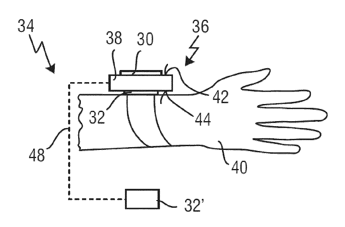
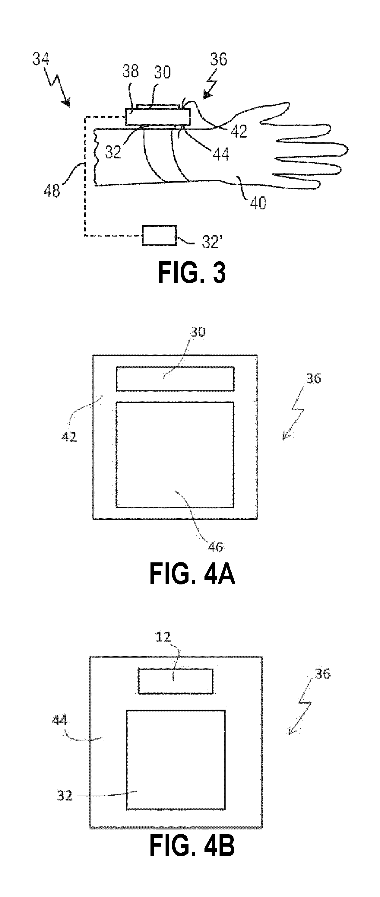
[0051]With reference to FIG. 3, a system 34 in accordance with a second embodiment is shown. The system 34 comprises a wearable device 10, wherein the wearable device 10 comprises a housing 36 that can be worn by the living being 14. In particular, the system 34 comprises a wristwatch-like device 36 with a housing 38 wearable on one wrist or arm of the living being 14. The first electrode 30 of the electrical sensing unit 28 is arranged on a first surface 42 of the housing 38, whereas the first surface 42 is not in contact with the wrist or arm 40 of the living being 14. The second electrode 32 of the electrical sensing unit 28 is arranged on a second surface 44 of the housing 38. The second surface 44 may be opposite to the first surface 42 with respect to the housing 38, so that the second electrode 32 may be configured to be in permanent contact with the skin of the wrist or arm 40.

[0052]In a preferable embodiment, one or more optical sensors 13, in particular PPG sensors, may be...

third embodiment

[0057]With reference to FIG. 5A a system 34 in accordance with a third embodiment is shown in a front view.

[0058]In this embodiment, the device 10 comprises a mobile communication device 50, in particular a smartphone. Alternatively, the mobile communication device 50 may be configured as a tablet, a calculator, a portable media player, a video camera or a navigation device. The first and second electrodes 30, 32 of the electrical sensing unit 28, in particular being an ECG unit, are advantageously arranged on a front surface 52 of the mobile communication device 50. Alternatively, the electrical sensing unit 28 may comprise further electrodes, wherein at least two of all electrodes of the electrical sensing unit 28 are arranged on two different surfaces of the mobile communication device 50. In particular, at least one electrode 30, 32 may be arranged on a back surface 54 or a side surface 56, 57, 58, 59, as shown in FIG. 5B.

[0059]The optical sensing unit 12 is arranged advantageou...


PUM


Abstract

The present invention relates to a system (34) for detecting variation of heart rate, HR, of a user (14), said system comprising an optical sensing unit (12) for measuring a heartbeat-related optical signal of said user (14) over time, a processing unit (20) for deriving an HR-variation signal from said heartbeat-related optical signal, an analyzing unit (22) for comparing said derived HR-variation signal to a reference HR range, and an initiating unit (26) for initiating a process for measuring an informative heartbeat-related signal of said user (14) depending on said comparing of said analyzing unit (22).

Description

FIELD OF THE INVENTION[0001]The present invention relates to detection of physiological signals of cardiovascular systems. In particular, it relates to a system and method for detecting variation of heart rate of a user. It finds applications in diagnostic investigation of arrhythmias, in particular in the detection of atrial fibrillation. However, it is to be understood that the present invention also finds applications in other fields and is not necessarily limited to the afore-mentioned applications.BACKGROUND OF THE INVENTION[0002]Cardiovascular diseases are a class of diseases that involve the circulatory system such as the heart, the blood vessels including arteries, capillaries and veins. Cardiovascular diseases include cardiac diseases, vascular diseases of the brain and kidney, and peripheral arterial diseases. Nowadays, cardiovascular diseases have become one of the leading causes of death for human worldwide. It is thus crucial to develop techniques that enable efficient ...

Claims


Application Information

Patent Timeline
Patent Type & Authority Applications(United States)
IPC IPC(8): A61B5/024A61B5/0464A61B5/044A61B5/0402A61B5/00A61B5/332A61B5/363
CPCA61B5/02405A61B5/0402A61B5/7285A61B5/02416A61B5/0464A61B5/681A61B5/02438A61B5/721A61B5/7475A61B5/044A61B5/0245A61B5/6802A61B5/746A61B5/6898A61B5/318A61B5/339A61B5/363
Inventor COPPOLA, GIUSEPPEHUIJBREGTS, LAURENTIA JOHANNA
Owner KONINKLJIJKE PHILIPS NV
Why Eureka
Try Eureka