Multi-stage variable gain amplifier utilizing overlapping gain curves to compensate for log-linear errors

a gain curve and variable gain technology, applied in amplifiers, amplifiers with semiconductor devices/discharge tubes, volume compression/expansion having semiconductor devices, etc., can solve the problem of not being able to achieve accurate exponential gain control for such continuous gain control loops, and achieve more log-linear response

Active Publication Date: 2006-08-29
SILICON LAB INC
View PDF10 Cites 2 Cited by
  • Summary
  • Abstract
  • Description
  • Claims
  • Application Information

AI Technical Summary

Problems solved by technology

Achieving accurate exponential gain control for such continuous gain control loops, however, is not easily achieved with CMOS circuitry.
However, these prior solutions are still attempting to fit as best possible a fundamentally non-log-linear gain response curve for each stage onto a desired log-linear response.

Method used


Image

  • Multi-stage variable gain amplifier utilizing overlapping gain curves to compensate for log-linear errors
  • Multi-stage variable gain amplifier utilizing overlapping gain curves to compensate for log-linear errors
  • Multi-stage variable gain amplifier utilizing overlapping gain curves to compensate for log-linear errors

Examples


Embodiment Construction

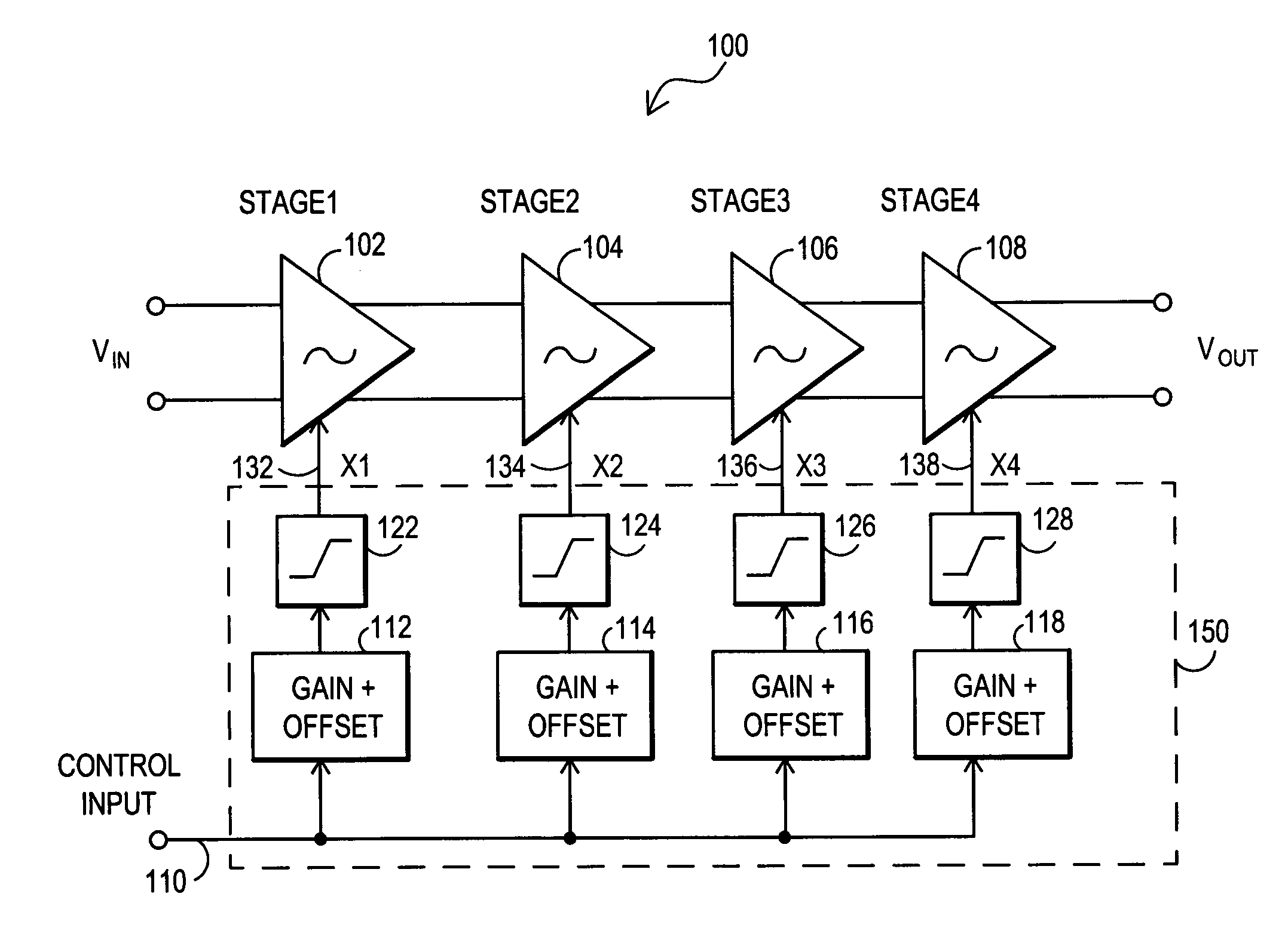
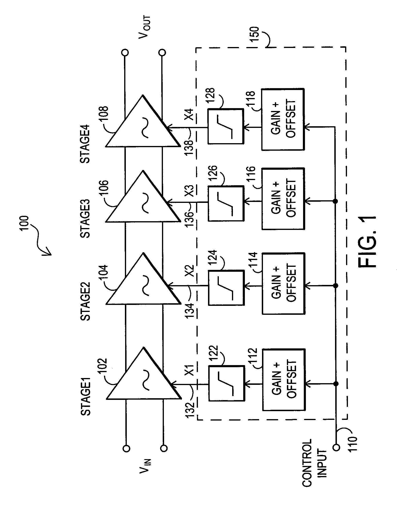
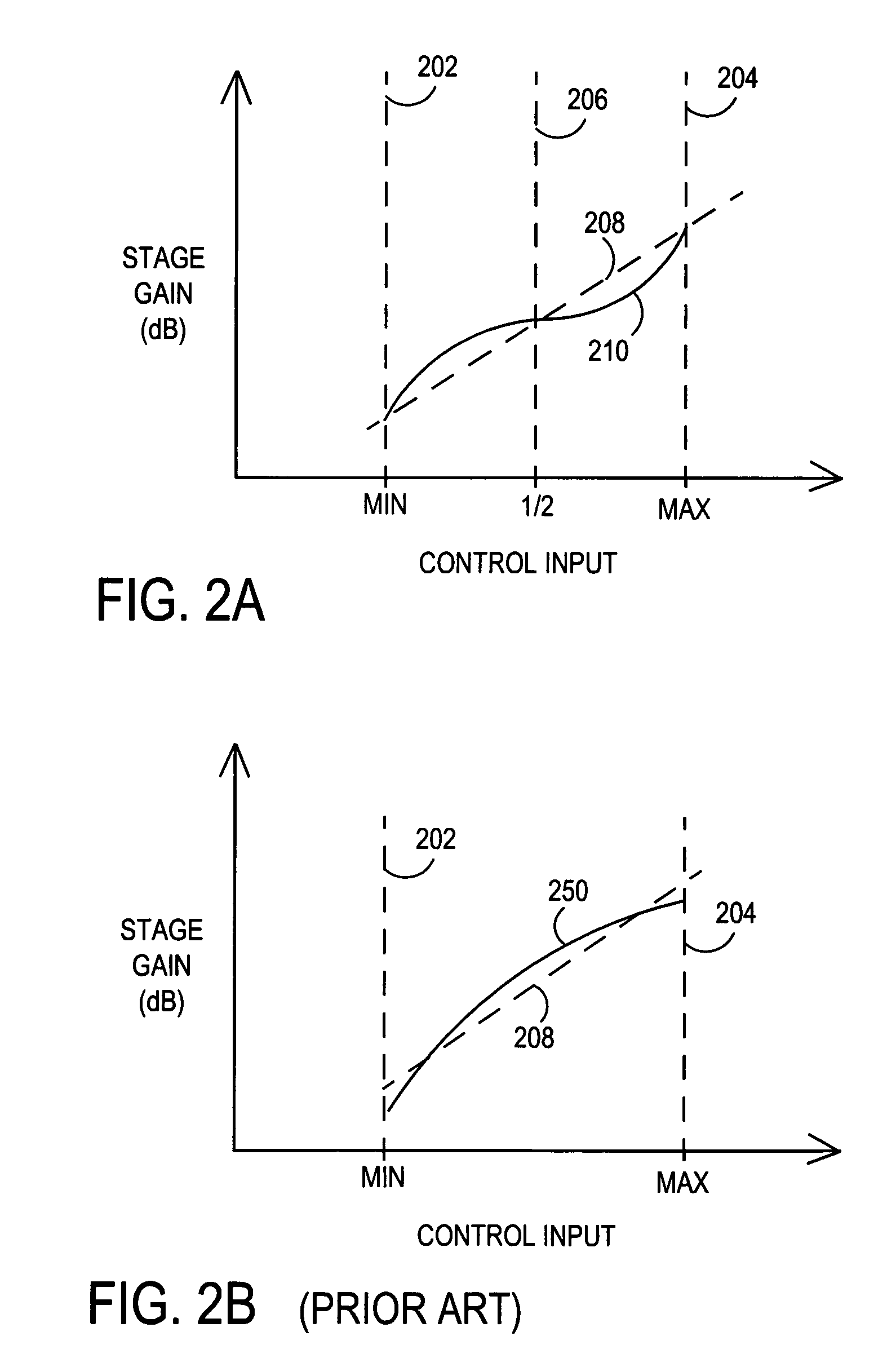
[0015]The present invention provides a multi-stage variable gain amplifier (VGA) that utilizes overlapping gain curves to compensate for log-linear errors. FIG. 1 provides a diagram of the VGA. FIG. 2A and FIG. 2B (prior art) provide a comparison of gain curves utilized by the present invention and prior systems. FIGS. 3A–3C provide example control signals and resulting gain responses according to the present invention. And FIG. 4 provides an example embodiment for the gain stages.

[0016]FIG. 1 is a block diagram for a multi-stage variable gain amplifier. In particular, embodiment 100 includes gain stages 102, 104, 106 and 108. Each of these gain stages is designed to approximate a log-linear response with a sinusoidal error term. This gain stages are controlled by respective gain control input signals (XI, X2, X3, X4) 132, 134, 136 and 138. The gain stages 102, 104, 106 and 108 act together to provide an output voltage VOUT that is an amplified version of the input voltage VIN. The ...


PUM


Abstract

A multi-stage variable gain amplifier is disclosed that utilizes overlapping gain curves to compensate for log-linear errors. Each gain stage is configured to approximate a log-linear response with a sinusoidal error term such that a portion of the curve has positive errors and a portion of the curve has negative errors. In operation, the control signal inputs for the gain stages are driven such that the gain curves overlap and positive errors in each stage are offset by negative errors in the adjacent stage. The resulting combined gain is a more log-linear response.

Description

TECHNICAL FIELD OF THE INVENTION[0001]This invention relates to variable gain amplifiers, and more particularly, this invention relates to multi-stage variable gain amplifiers.BACKGROUND[0002]A variable gain amplifier (VGA) is an amplifier that has a signal gain (Av) determined by a control input. VGAs are utilized in communication systems and other electronic systems where an input signal level varies over a wide dynamic range. The VGA is often embedded inside of an automatic gain control (AGC) feedback loop which attempts to maintain the output signal level nearly constant even though the level of the input signal varies over time. When operating in a feedback loop, a VGA with exponential gain control characteristics is usually desirable for its large dynamic control range, constant loop settling time independent of absolute gain, and the ability to use the control signal as a logarithmic received signal strength indicator. It is also typically important to minimize the variation ...

Claims


Application Information

Patent Timeline
Patent Type & Authority Patents(United States)
IPC IPC(8): H03G5/16
CPCH03G7/06
Inventor DUPUIE, SCOTT T.
Owner SILICON LAB INC
Why Eureka
Try Eureka