
DAC current source matrix patterns with gradient error cancellation

a current source and gradient error technology, applied in the field of digital to analog converters, can solve the problems of affecting the accuracy of the dac, requiring additional space, and typically complex circuitry for calibration, and achieve the effect of reducing the first order gradient

Active Publication Date: 2015-07-28
SKYWORKS SOLUTIONS INC
View PDF4 Cites 1 Cited by
  • Summary
  • Abstract
  • Description
  • Claims
  • Application Information

AI Technical Summary

Benefits of technology

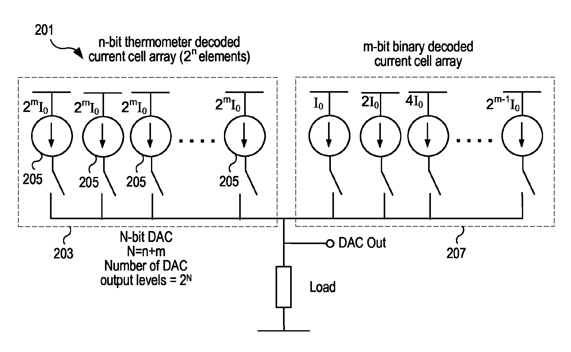
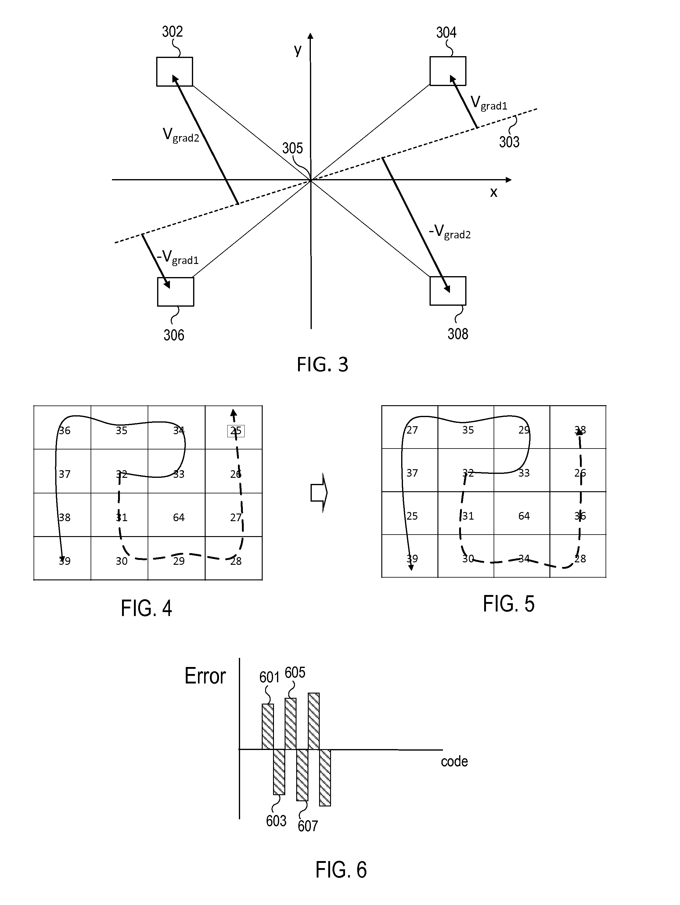
The patent describes a digital-to-analog converter (DAC) that uses a current array to convert digital signals to analog signals. The DAC includes multiple pairs of current elements that are arranged in a way that reduces errors caused by changes in the input code. The first current element of each pair is placed with a positive error, while the second current element is placed with a negative error that is approximately the same as the first element's error. The current elements are also symmetrically placed to reduce first order gradient effects. The method of operating the DAC involves turning on the first current element of each pair responsive to the input code, and then turning on the second current element of each pair responsive to a thermometer code step. This reduces the second order gradient effects of the first current element by turning on the second current element of each pair. Overall, this design and method improve the accuracy and reliability of the DAC.

Problems solved by technology

One problem with DACs is that gradients in the integrated circuit due to, e.g., process or temperature can impact the accuracy of the DAC.
Calibration of the DAC can be used to address such gradients, but such calibration typically requires complex circuitry and additional space that can be undesirable for certain DAC applications.

Method used


Image

  • DAC current source matrix patterns with gradient error cancellation
  • DAC current source matrix patterns with gradient error cancellation
  • DAC current source matrix patterns with gradient error cancellation

Examples


Embodiment Construction

[0006]In an embodiment, first order gradient errors are canceled with no current source splitting. Consecutive current sources are placed symmetrically around the center of the array such that consecutive elements cancel the accumulated mismatch. The element placement may also follow a constraint that the consecutive elements that correspond to small input amplitudes (mid-scale codes) make a smaller spatial jump than those that correspond to larger signal amplitudes.

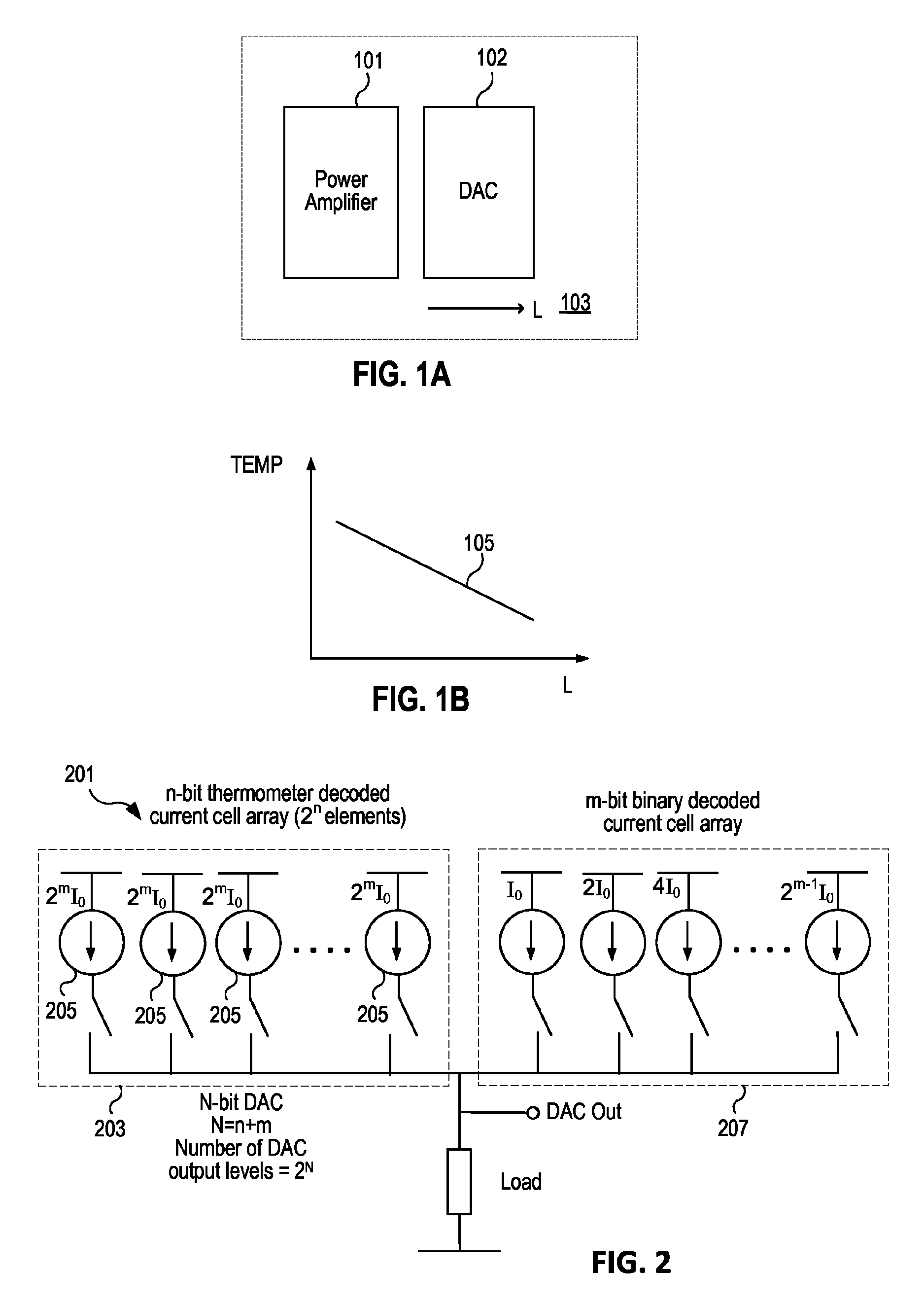
[0007]In an embodiment a digital-to-analog converter (DAC) includes an array of current elements configured to supply current using thermometer decoding of a code corresponding to at least a portion of a digital signal to be converted. For a majority of current elements in the array, pairs of consecutive current elements of the array are placed substantially symmetrically around a center location in the array, such that for each of the pairs, a first and second current element are offset from the center of the array in a...


PUM


Abstract

First order gradient errors are canceled with no current source splitting by placing consecutive current sources symmetrically around the center of the array. Consecutive elements that correspond to small input amplitudes (mid-scale codes) make a smaller spatial jump than those correspond to larger signal amplitudes. Both linear and second order gradients are reduced by splitting each current cell into two and placing sub-elements symmetrically with respect to the center of the array to address the linear gradient effect. To address second order gradients, current element placement follows a pattern such that consecutive element pairs are chosen with one of the pair being placed with respect to the zero error contour of the second order gradient so as to have a positive error and the second of the pair being placed so as to have a negative error resulting in reduced second order error accumulation.

Description

BACKGROUND[0001]1. Field of the Invention[0002]This invention relates to digital-to-analog converters (DACs) and more particularly to gradient error cancellation associated with digital-to-analog converters.[0003]2. Description of the Related Art[0004]One problem with DACs is that gradients in the integrated circuit due to, e.g., process or temperature can impact the accuracy of the DAC. For example, referring to FIG. 1A, a power amplifier 101 that generates heat adjacent to a DAC 102 in an integrated circuit 103 may cause a temperature gradient in the integrated circuit as shown in FIG. 1B. For simplicity, in the figure it is assumed that the temperature decreases linearly as distance from the heat source increases as illustrated by line 105. While a linear temperature gradient is shown, threshold voltage or other parameters may also increase or decrease across the device that can be approximated by a linear gradient (first order) or quadratic (second order) or even higher order gr...

Claims


Application Information

Patent Timeline
Patent Type & Authority Patents(United States)
IPC IPC(8): H03M1/66
CPCH03M1/66H03M1/0648H03M1/687H03M1/745H03M1/747
Inventor ONODY, PETERCOBAN, ABDULKERIM L.
Owner SKYWORKS SOLUTIONS INC
Learn More