
Power window switch apparatus

a technology of power window switch and switch body, which is applied in the direction of contact mechanism, transportation and packaging, windows, etc., can solve the problem of b>11/b> being damaged

Active Publication Date: 2006-09-05
KK TOKAI RIKA DENKI SEISAKUSHO
View PDF28 Cites 2 Cited by
  • Summary
  • Abstract
  • Description
  • Claims
  • Application Information

AI Technical Summary

Benefits of technology

[0011]In view of the above problem, an object of the present invention is to provide a power window switch that prevent the abnormal state from occurring even if the damage occurs at the stopper which restricts the rotation of the operating knob to the predetermined angle.
[0021]According to the present invention, since the second stopper restrict the rotation of the operating knob to the predetermined angle even if the first stopper is damaged, the abnormal state can be prevented any more.

Problems solved by technology

Therefore, there is a fear that the stopper 11 be damaged due to fatigue by a long-term use. FIG. 8 shows such a state.

Method used


Image

  • Power window switch apparatus
  • Power window switch apparatus
  • Power window switch apparatus

Examples


Embodiment Construction

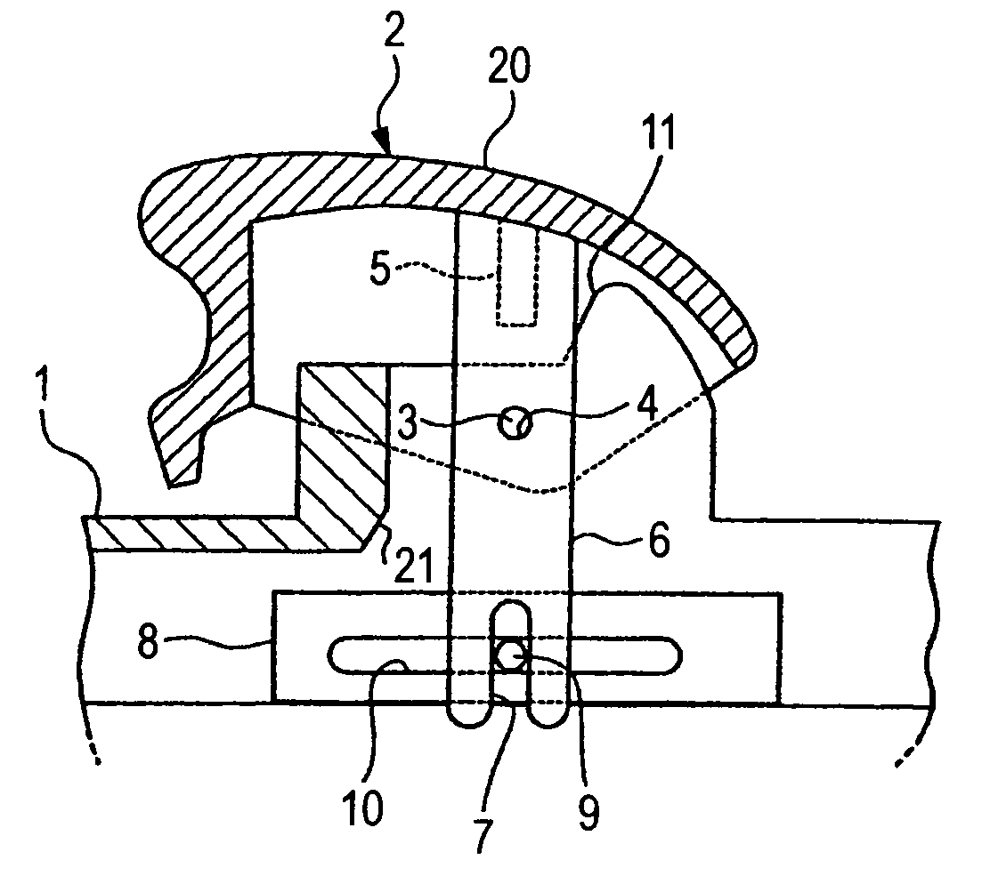
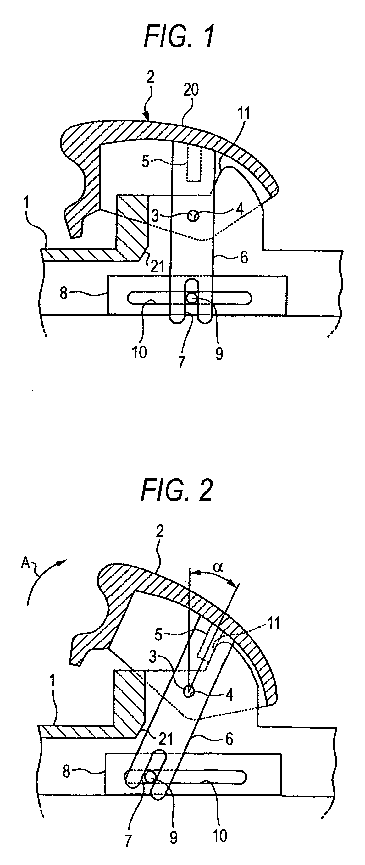
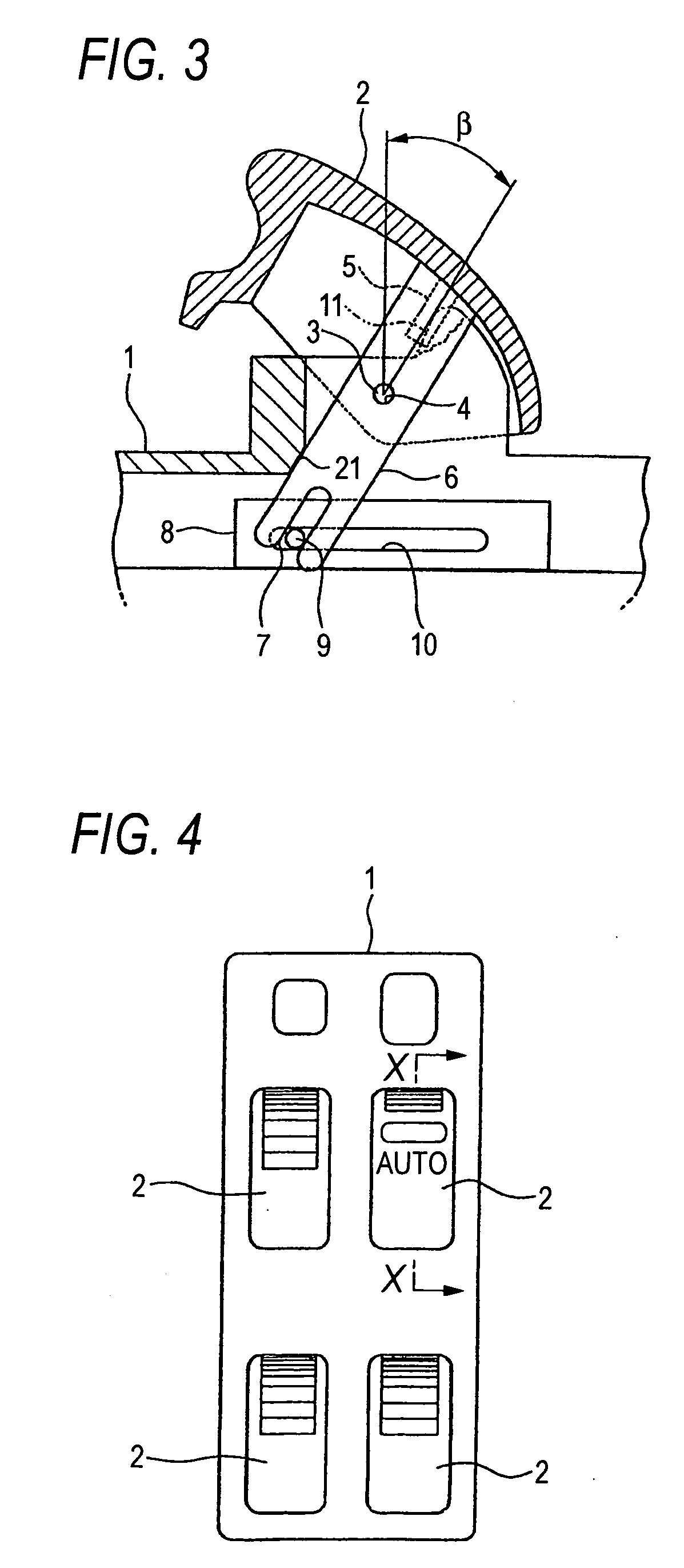
[0031]An embodiment according to the present invention will be described hereinafter with reference to FIGS. 1 to 3.

[0032]Component parts shown in FIG. 1 substantially similar to those in the related art shown in FIGS. 4 to 9 are given same reference number and the description thereof will be omitted. The embodiment according to the invention differs from the related art in that a second stopper 21 is provided to the switch body 1 in addition to the stopper 11. For ease of the explanation, the stopper 11 is called as a first stopper hereinafter. The second stopper 21 and the first stopper 11 are substantially symmetrical with a point of the shaft 3 (hole 4). A portion close to the distal end of the operating rod 6 corresponds to the second stopper 21. A predetermined rotating angle β described later of the operating knob 2 when the portion close to the distal end of the operating rod 6 is abutted against the second stopper 21 is set larger than the predetermined rotating angle α of ...


PUM


Abstract

A power window switch apparatus includes: a switch body; a operating knob pivotally supported by the switch body; a first stopper that is provided to the switch body and restricts a rotation of the operating knob to a first predetermined angle; and a second stopper that is provided to the switch body and restricts the rotation of the operating knob to a second predetermined angle when the first stopper becomes impossible to restrict the rotating of the operating knob.

Description

BACKGROUND OF THE INVENTION[0001]The present invention relates to a power window switch apparatus in which a rotating angle restricting structure of an operating knob is improved.[0002]Generally, in a power window switch apparatus of a vehicle, especially automobile, as shown in FIGS. 4 and 5, operating knobs 2 are pivotally supported by a switch body 1 through shafts 3 (pivot). The operating knobs 2 includes at opposite side surfaces thereof the shafts 3 or holes 4 to be engaged with the shafts 3, and further includes an projection 5 and an operation rod 6 which are projected downwardly from an inner upper portion thereof. A fork-shaped engaging portion 7 is formed at a distal end of the operating rod 6 relatively extended from the projection 5. The operating knob 2 includes an operating portion 20 through which an operator can operates the operating knob 2.[0003]On the other hand, a switch module 8 is provided inside the switch body 1. Although the detail is not shown in the drawi...

Claims


Application Information

Patent Timeline
Patent Type & Authority Patents(United States)
IPC IPC(8): H01H3/00B60J1/17H01H3/16H01H3/46H01H19/635H01H21/02H01H21/04H01H21/36H01H23/24
CPCH01H21/22H01H2300/01H01H2021/225H01H2009/0083
Inventor HISHIKAWA, KOJI
Owner KK TOKAI RIKA DENKI SEISAKUSHO
Learn More