Extreme sports ramp system

a technology for ramps and extreme sports, applied in the direction of amusements, construction, skiing, etc., can solve the problems of uneven surface, lack of safety inherent in make-shift non-engineered structures, and labor required to construct and de-constru

Inactive Publication Date: 2006-09-12
HICKEY ROGER WILLIAM
View PDF5 Cites 13 Cited by
  • Summary
  • Abstract
  • Description
  • Claims
  • Application Information

AI Technical Summary

Problems solved by technology

Currently utilized structures range from a board elevated at one end used by beginners to large bulky completely pre-assembled and very heavy one-piece structures.
The problems thus encountered involve (1) the amount of labor necessary to construct and de-construct the more sturdy ramp structures, (2) the lack of safety inherent in make shift non-engineered structures, not only from falling over but in their lack of provision of an even surface, (3) the space occupied by a structure which cannot be dis-assembled in transport, (4) the space occupied by a structure which can be dis-assembled, (5) the ability to alter the size and shape of the ramp, (6) the provision of a ramp which is enabled to evenly distribute its support load handling capability, and (7) the design to enable the structures to fit together in many different configurations.
Where an assembly-required ramp kit includes the possibility that structure will be omitted or not assembled consistently, an uneven surface will likely result.
Transport and storage is another problem both with regard to manufacturing and transport to a sales venue, as well as normal stowage and deployment throughout the useful life.
If the space occupied by a structure disassembled for stowage is not as small as is practicable, additional transport costs will result in a hidden utilization costs.
Most conventional ramps are fixed, stand-alone units and do not have the ability to have their size and shape altered.
Most conventional ramps which are fabricated without plans or without strict adherence to plans result in a ramp which has no ability to evenly distribute its support load handling capability.
Most ramps are not engineered to be lightweight, requiring no more than one person to set up, move, fold up and store away.

Method used


Image

  • Extreme sports ramp system
  • Extreme sports ramp system
  • Extreme sports ramp system

Examples


Embodiment Construction

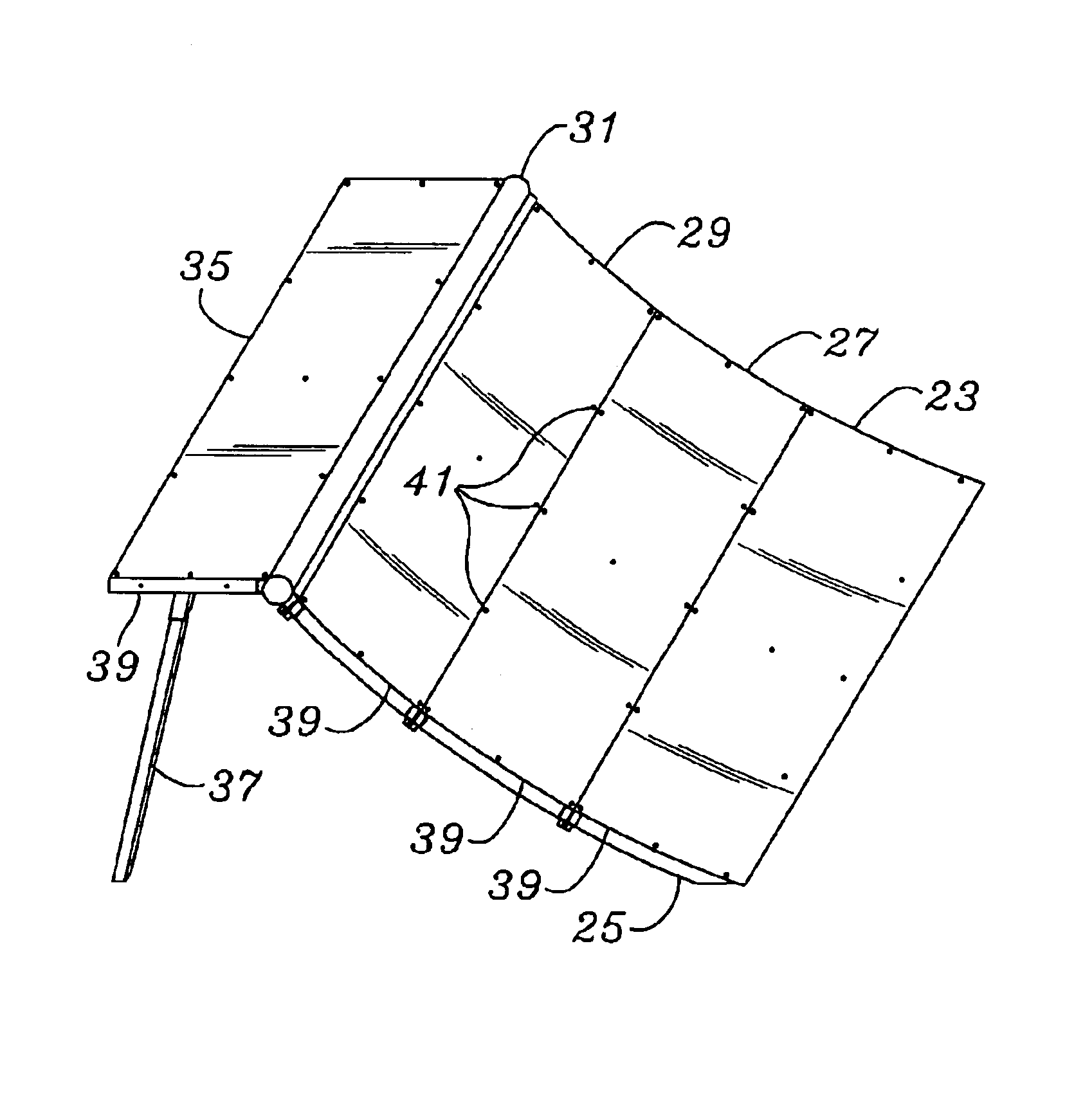
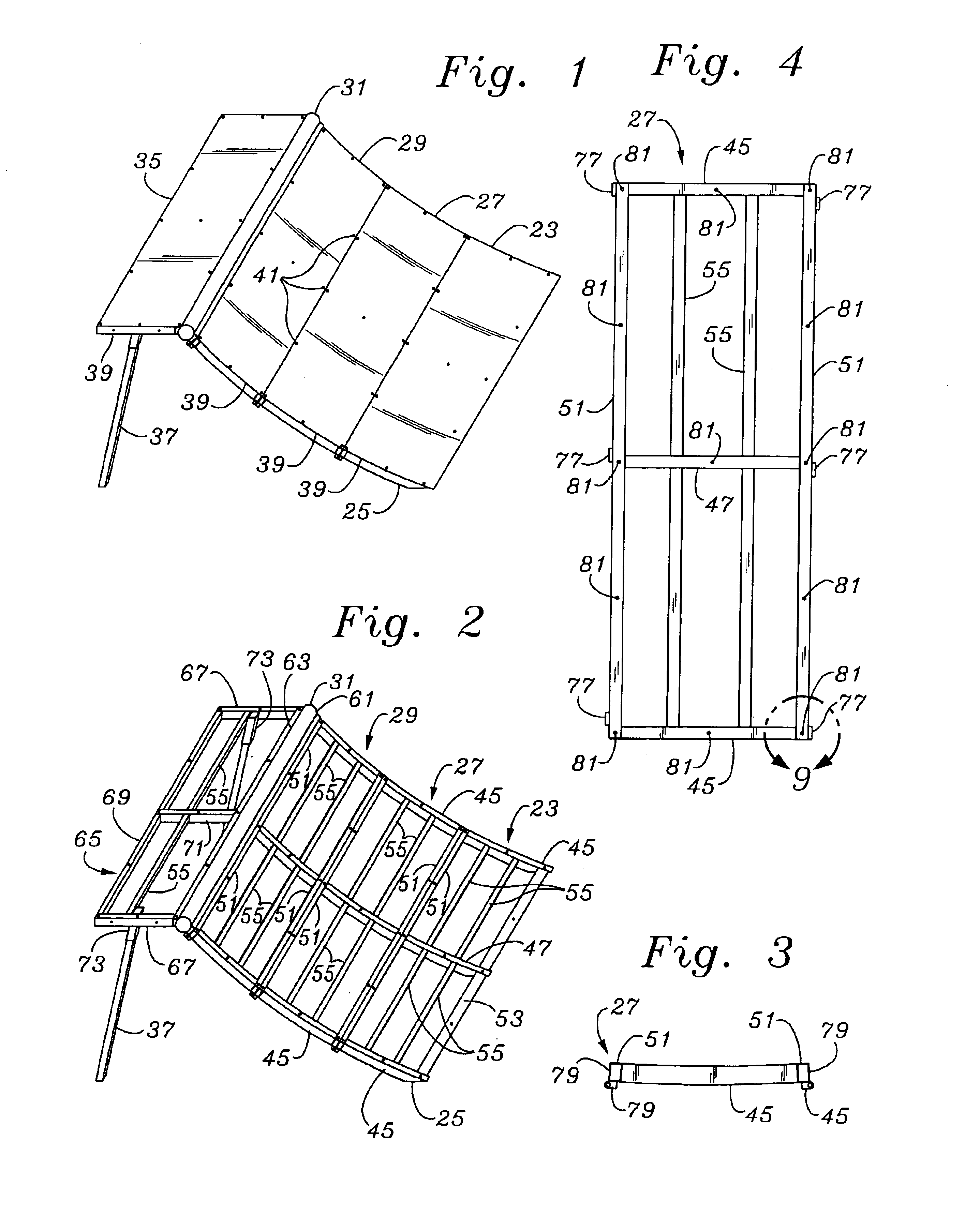
[0020]The description and operation of the ramp system of the invention will be best described with reference to FIG. 1 which illustrates a perspective view of a base configuration of a ramp system 21. The main sections of the ramp system as seen in this perspective view, from the bottom, include a lower section 23 showing an angled portion 25 to facilitate interface with the ground, a middle section 27 and a top section 29. Adjacent the top section 29 is a curved rail 31 which expresses a cylindrical section and extends the full width of the ramp system 21.

[0021]Adjacent the curved rail 31 is a nearly horizontal deck 35. One of the support legs 37 which extends from a position nearly mid-width of the deck section 35 is seen as having a slight angle with respect to the deck 35. The angle of support legs assists support of the deck 35 as users place force against the sections 23, 27 and 29. The sections 23, 27 and 29 are nearly indistinguishable because of the close fit and the fact ...


PUM


Abstract

A compact, hinged, foldably deployable ramp is provided in a base configuration which includes three evenly radiused sections which connect to a deck member and have a tube, known as a coping, separating the ramp from the deck. In the base configuration, a top section, mid section and lower section each have a pair of ladder structures which share a middle flange. The deck member includes a pair of angled leg members which are designed to provide support throughout the range of engagement of the ramp. Even size and radiusing of the sections enables continued extension of the ramp by adding sections in conjunction with longer support legs for the deck.

Description

FIELD OF THE INVENTION[0001]The present invention relates to an improvements in providing a stowable, rapidly deployable, modular sports ramp especially valuable for creating various touring setups, and more particularly to a configuration which is easily packed and able to be shipped in palates and which can withstand the extreme forces generated by the use of skateboards, in-line skates, scooters and bicycles while providing a radiused and smooth segment transition.BACKGROUND OF THE INVENTION[0002]Extreme sports ramps are used in conjunction with skateboards, in-line skates, scooters and bicycles to enable participants to do tricks and to apply controlled upward and downward force along with lateral movement and force. Currently utilized structures range from a board elevated at one end used by beginners to large bulky completely pre-assembled and very heavy one-piece structures. For professionals, it is not unusual for exhibitors of professional talent to carry a crew of carpente...

Claims


Application Information

Patent Timeline
Patent Type & Authority Patents(United States)
IPC IPC(8): A63C19/10
CPCA63C19/10A63C2203/10
Inventor HICKEY, ROGER WILLIAM
Owner HICKEY ROGER WILLIAM
Why Eureka
Try Eureka