Communicating a channel-change event from a set top box to a digital video recorder

a technology of digital video recorder and channel change, which is applied in the field of digital video recorders, can solve problems such as affecting the proper operation of dvr

Active Publication Date: 2006-09-12
KEEN PERSONAL MEDIA
View PDF12 Cites 142 Cited by
  • Summary
  • Abstract
  • Description
  • Claims
  • Application Information

AI Technical Summary

Problems solved by technology

Prior art DVRs have no way of knowing if the user has changed the channel by controlling the STB 4 directly which can disrupt the proper operation of the DVR 2.

Method used


Image

  • Communicating a channel-change event from a set top box to a digital video recorder
  • Communicating a channel-change event from a set top box to a digital video recorder
  • Communicating a channel-change event from a set top box to a digital video recorder

Examples


Embodiment Construction

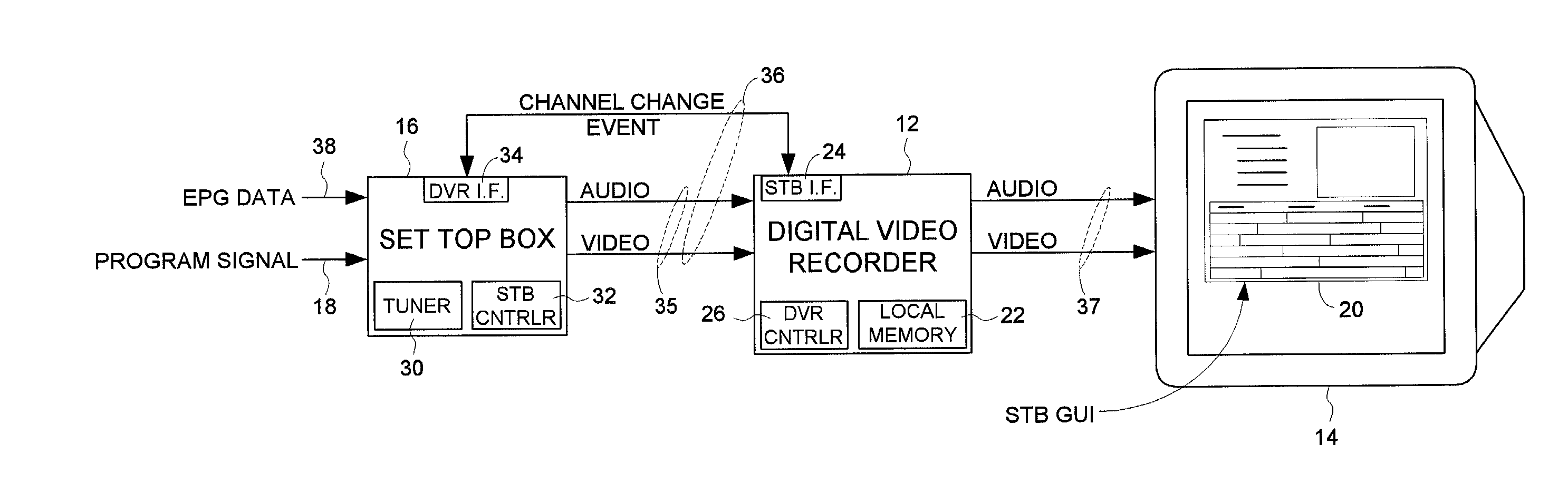
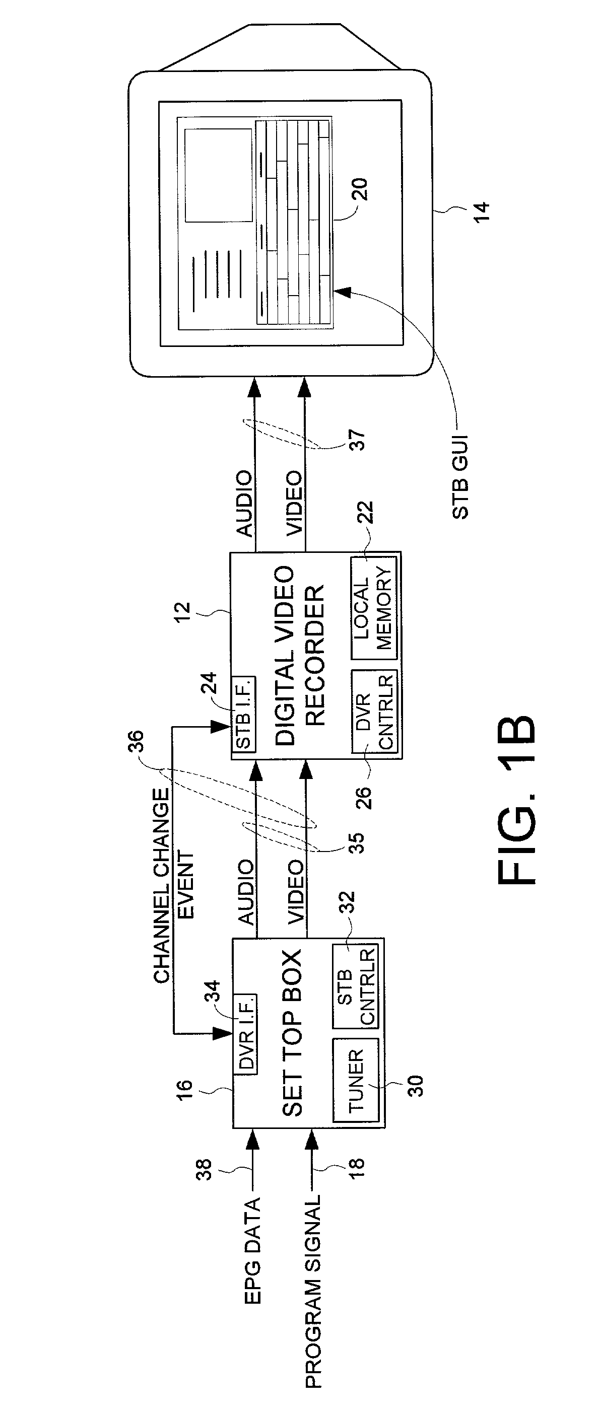
[0028]FIG. 1B shows a digital video recorder (DVR) 12 for use with a monitor 14 and a set top box (STB) 16 according to an embodiment of the present. The STB 16 for demodulating program data by tuning to at least one of a plurality of channels, and the STB 16 comprising a DVR interface 34. The DVR 12 comprises a local memory 22 for storing the program data received from the STB 16, and a STB interface 24 for communicating with the STB over the DVR interface 34. The DVR 12 further comprises a DVR controller 26 for communicating control data to direct the STB to tune to a selected channel, and for receiving a channel-change event from the STB 16 in connection with the STB 16 changing the tuned channel.

[0029]In one embodiment, the channel-change event is received by the DVR 12 after the STB 16 changes the tuned channel. In another embodiment, the channel-change event is received by the DVR 12 when a user directs the STB 16 to change the tuned channel and before the STB 16 changes the t...


PUM

PropertyMeasurementUnit
frequencyaaaaaaaaaa
optical frequenciesaaaaaaaaaa
timeaaaaaaaaaa

Abstract

A digital video recorder (DVR) for use with a monitor and a set top box (STB) is disclosed. The STB demodulates program data by tuning to at least one of a plurality of channels and comprises a DVR interface. The DVR comprises a local memory for storing the program data received from the STB, and a STB interface for communicating with the DVR interface. The DVR further comprises a DVR controller for communicating control data to direct the STB to tune to a selected channel, and for receiving a channel-change event from the STB in connection with the STB changing the tuned channel.

Description

CROSS REFERENCE TO RELATED APPLICATIONS AND PATENTS[0001]This application is related to co-pending U.S. patent application Ser. No. 09 / 652,730 filed on Aug. 31, 2000 entitled “ELECTRONIC PROGRAM GUIDE SUBSYSTEM FOR RECEIVING AND PROCESSING ELECTRONIC PROGRAM GUIDE INFORMATION FROM A SET-TOP BOX”, the disclosure of which is herein incorporated by reference.BACKGROUND OF THE INVENTION[0002]1. Field of the Invention[0003]The present invention relates to digital video recorders. More particularly, the present invention relates to communicating a channel-change event from a set top box to a digital video recorder.[0004]2. Description of the Prior Art[0005]FIG. 1A shows a prior art digital video recorder or DVR 2 installed between a set top box 46 or STB 4 (e.g., a tuner for digital cable) and a monitor 6. The STB 4 demodulates a selected channel from a program signal 5 and provides an audio and video (A / V) signal 7 to the DVR 2. The DVR 2 may record the A / V signal 7 for playback at a lat...

Claims


Application Information

Patent Timeline
Patent Type & Authority Patents(United States)
IPC IPC(8): H04N5/91G11B31/00H04N5/76H04N5/765H04N5/775H04N5/782H04N21/41H04N21/434H04N21/436H04N21/438H04N21/472
CPCH04N5/76H04N5/775H04N21/47214H04N21/4345H04N21/43615H04N21/4383H04N21/4135H04N5/765H04N5/782
Inventor BOYLE, WILLIAM B.PRICE, WILLIAM P.
Owner KEEN PERSONAL MEDIA
Why Eureka
Try Eureka