Spherical retro-reflector mount negative

a retro-reflector and negative technology, applied in the field of precision optical element mounts, can solve the problems of reducing the effective size of the circular opening or aperture and rendering measurement readings more difficult to obtain, and achieve the effect of high degree of precision

Inactive Publication Date: 2006-09-19
HUBBS MACHINE & MFG
View PDF5 Cites 30 Cited by
  • Summary
  • Abstract
  • Description
  • Claims
  • Application Information

AI Technical Summary

Problems solved by technology

However, as can be seen in FIG. 5, a portion of the circular opening or aperture to the ball mounted retro-reflector is occluded by the modified sphere mount, reducing the effective size of the circular opening or aperture and rendering measurement readings more difficult to obtain.

Method used


Image

  • Spherical retro-reflector mount negative
  • Spherical retro-reflector mount negative
  • Spherical retro-reflector mount negative

Examples


Embodiment Construction

[0025]The following detailed description illustrates the invention by way of example and not by way of limitation. The description clearly enables one skilled in the art to make and use the invention, describes several embodiments, adaptations, variations, alternatives, and uses of the invention, including what is presently believed to be the best mode of carrying out the invention.

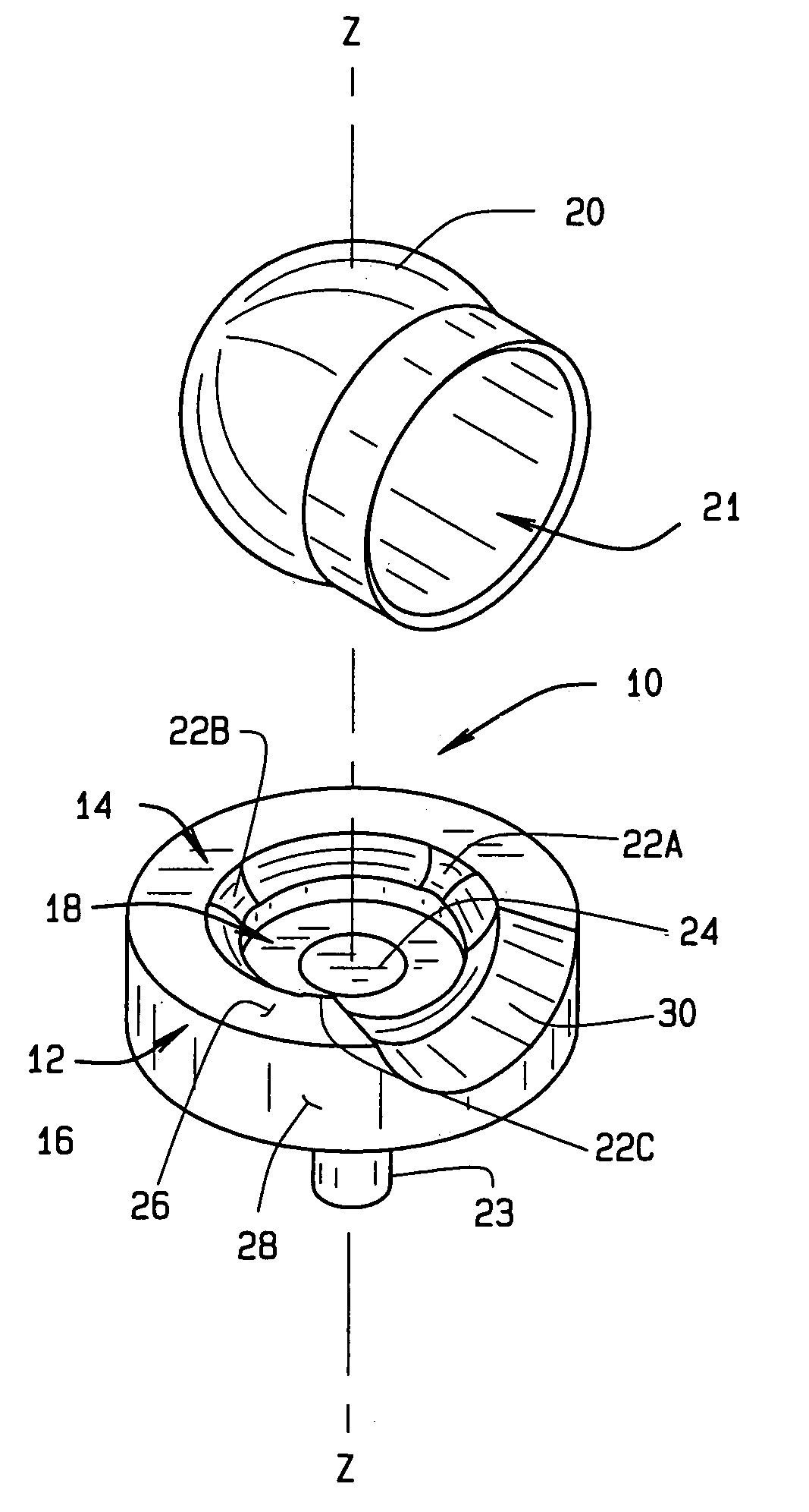
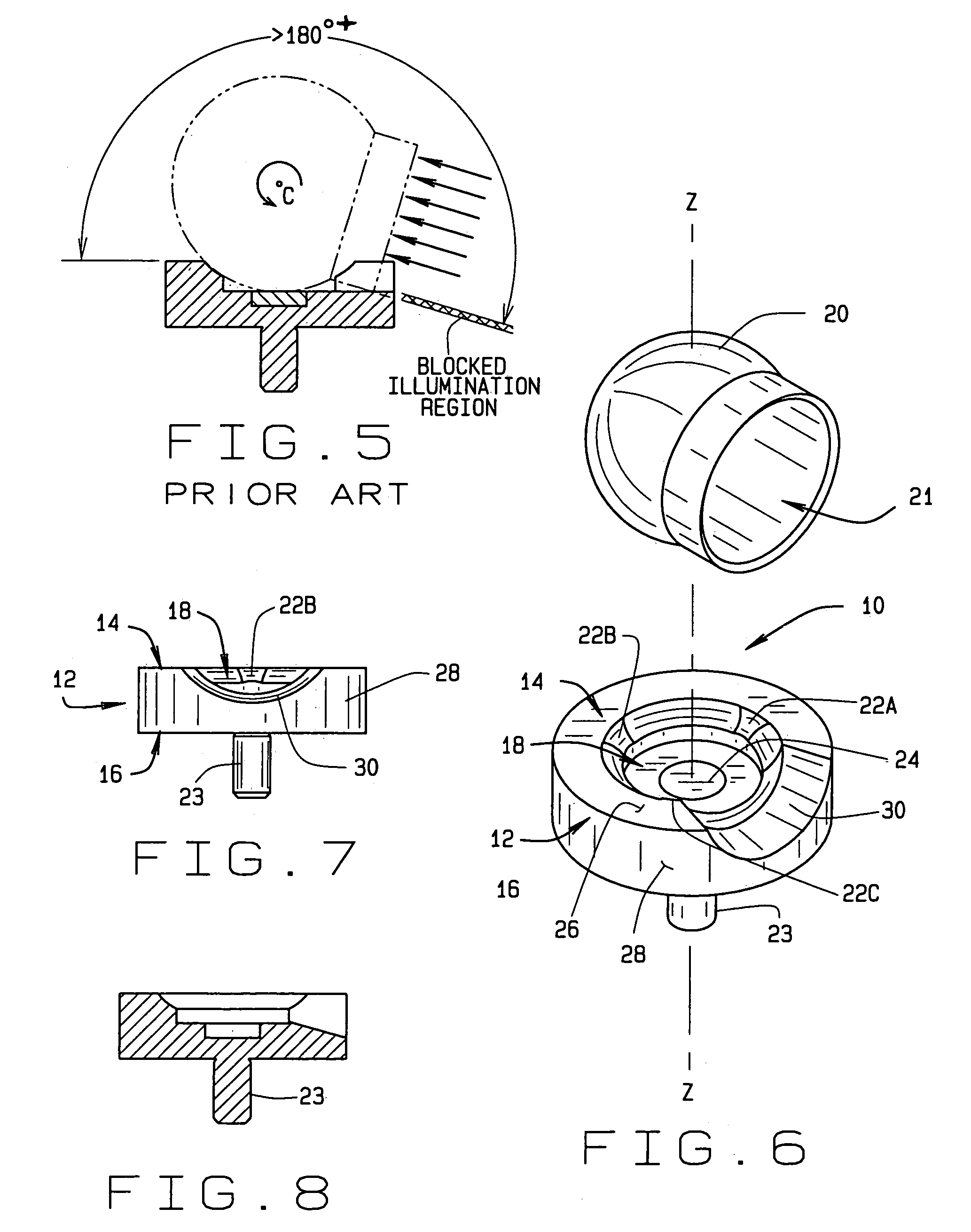
[0026]Turning to FIG. 6 through FIG. 8, a sphere mount of the present invention is shown generally at 10. Sphere mount 10 comprises a cylindrical body 12, having an upper surface 14 and a lower surface 16 disposed perpendicular to a central axis Z—Z. A conical nest 18 is disposed in the upper surface 14, and is configured to receive a ball mounted retro-reflector 20 of predetermined diameter, having an circular opening 21 through which incident and reflected light passes. A cylindrical base shank 23 extends perpendicularly from the lower surface 16, concentric with the central axis Z—Z to within a predete...


PUM


Abstract

A sphere mount for a ball mounted retro-reflector having a perimeter recess and a base shank. The sphere mount is configured to receive a ball mounted retro-reflector in a centrally disposed conical nest, such as a three-point conical nest, and to position it with a high degree of precision over the central axis of the base shank to within ±0.0005 of an inch. The perimeter recess is in the form of a single oblique scallop, orientated from the upper surface to the lower surface, and permits a maximum negative acceptance angle for incident light to a mounted spherical retro-reflector with no occlusion by the sphere mount perimeter.

Description

CROSS-REFERENCE TO RELATED APPLICATIONS[0001]This non provisional patent application claims priority to the provisional patent, application having Ser. No. 60 / 429,398, which was filed on Nov. 27, 2002.STATEMENT REGARDING FEDERALLY SPONSORED RESEARCH[0002]Not ApplicableBACKGROUND OF THE INVENTION[0003]The present invention relates to mounts for precision optical elements, and in particular, to a spherical retro-reflector three-point conical nest sphere mount, having a negative acceptance angle.[0004]Modern manufacturing technology, particularly that associated with the construction of large composite material structures, requires the contours of components and tooling to be accurately measured and inspected for compliance with design models and specifications. One manner in which these structures are measured is with the aid of portable coordinate measuring machines such as laser trackers.[0005]Laser trackers measure and inspect large components by illuminating one or more retro-refl...

Claims


Application Information

Patent Timeline
Patent Type & Authority Patents(United States)
IPC IPC(8): G02B7/02G02B5/12G02B7/182
CPCG02B7/182G02B5/12
Inventor HUBBS, WILLIAM O.
Owner HUBBS MACHINE & MFG
Why Eureka
Try Eureka