Wheel hub

a technology of hubs and wheels, applied in the direction of brake types, mechanical equipment, transportation and packaging, etc., can solve the problems of thermal stress lubricants, significant heat is necessary for the development of the wheel bearings, and hinders the dissipation of frictional heat occurring in the wheel, so as to improve the improve the effect of heat discharge to the environmen

Inactive Publication Date: 2006-09-26
KNORR-BREMSE SYST FUER NUTZFAHRZEUGE GMBH
View PDF10 Cites 41 Cited by
  • Summary
  • Abstract
  • Description
  • Claims
  • Application Information

AI Technical Summary

Problems solved by technology

Such wheel hubs have the problem of thermal stress to the wheel bearings and the lubricant as a result of a heat development in the wheel bearing as well as, under certain circumstances, also because of the heat transmission from the brake disk to the hub body.
In the case of a high loading of the vehicle, considerable heat is necessarily developed in the wheel bearing because of the resulting friction in the bearing.
In contrast, the enveloping of the hub body by the brake disk neck is less optimal, which enveloping, on the one hand, results in a thermal radiation from the brake disk neck to the surface of the hub body and, on the other hand, hinders the dissipating of the frictional heat occurring in the wheel bearing to the environment.
In the case of this type of construction, in addition to the limited heat dissipation by way of the surface area of the hub because of the enveloping by the brake disk neck, there is the problem that the hub part is separated from the wheel flange by the brake disk clamped in-between, and the heat dissipation capacity of the wheel flange is therefore not utilized for the hub.

Method used


Image

  • Wheel hub
  • Wheel hub
  • Wheel hub

Examples


Embodiment Construction

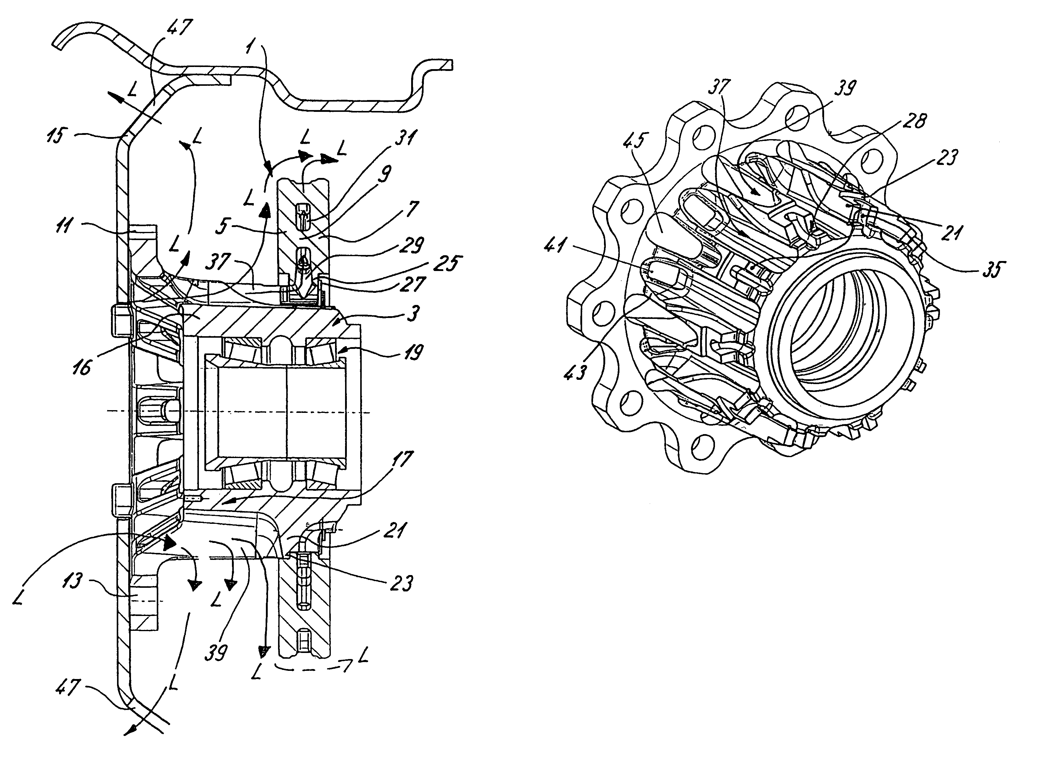
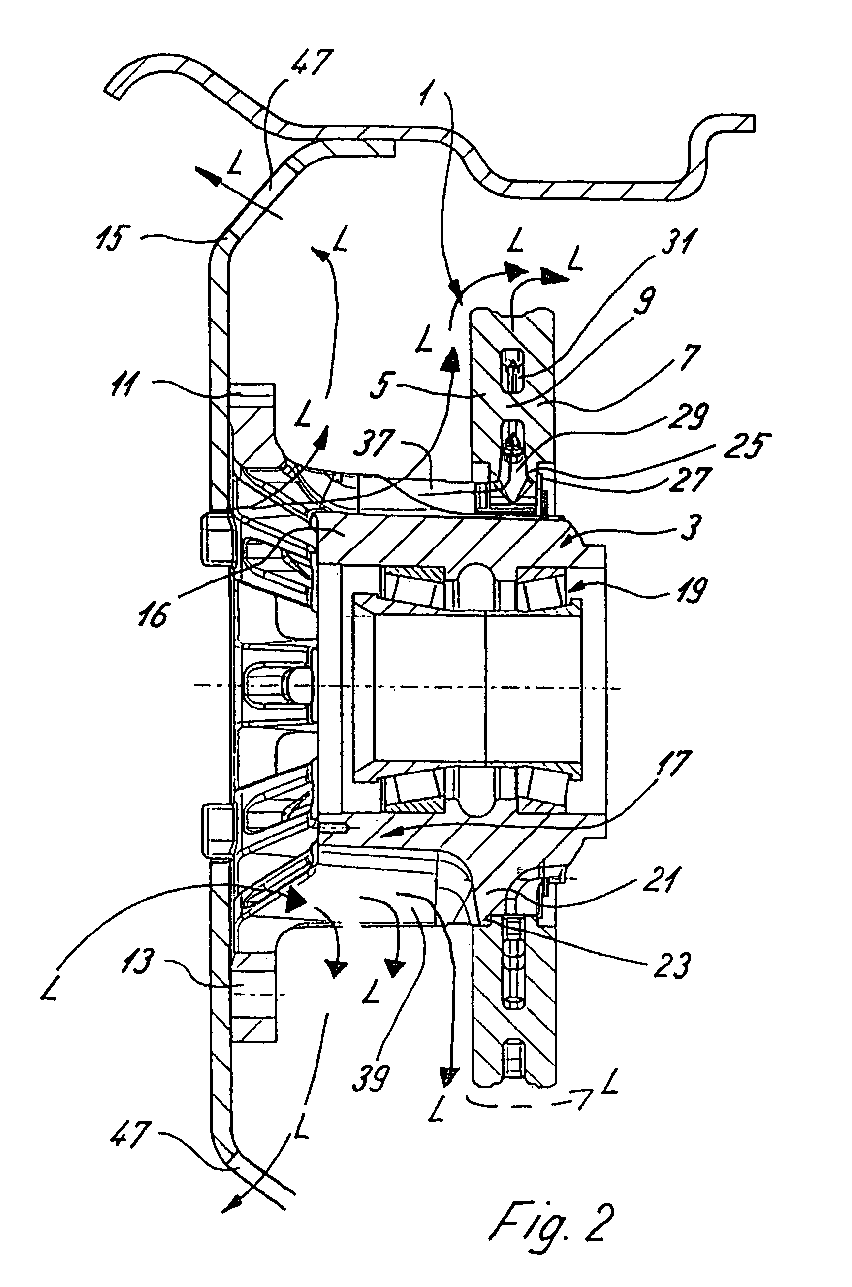
[0027]The internally ventilated brake disk 1 illustrated in FIG. 2 has two friction rings 5, 7 which are mutually connected by way of webs 9.

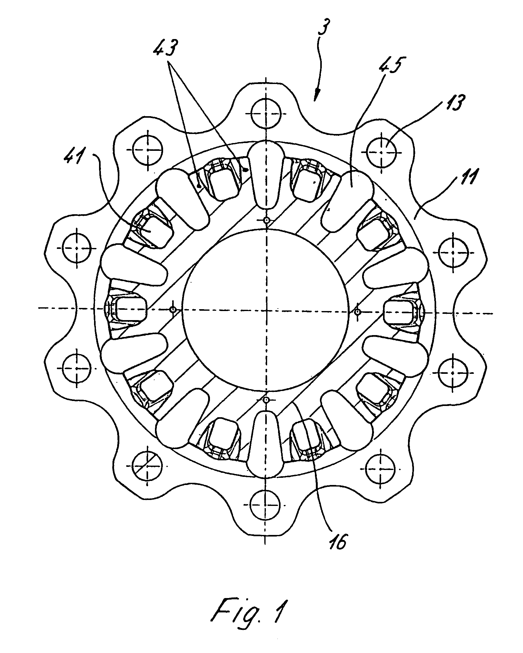
[0028]In contrast, the wheel hub 3 with the hub body 16 according to FIGS. 1 to 5 has an integrated wheel flange 11 with bores 13 for bolts (not shown here), by means of which the wheel hub 3 can be screwed to a wheel disk 15. The wheel flange 11 is adjoined by a hollow-cylindrical neck section 17 which is connected in one piece with the wheel flange 11—and slightly tapers here—and which, at its end facing away from the wheel flange 11, is placed with its interior circumference on a wheel bearing arrangement 19 which, in turn, can be placed on a shaft which is not shown here. At its end facing away from the wheel flange, the outer circumference of the neck section 17 is constructed such that the brake disk 1 can be placed thereon. For this purpose, the neck section 17 has cams 21 on its outer circumference, which cams 21 have one collar 23 resp...


PUM


Abstract

A wheel hub, especially a wheel hub for commercial vehicles, for receiving a brake disk, in which a neck section which is formed on the wheel flange for receiving the brake disk, the neck section being provided with a surface structure, preferably ribs, which increases the amount of heat given off to the environment. There may also be provided ducts between the ribs to permit cooling air to pass between the wheel flange and the brake disk to further increase the amount of heat given off to the environment.

Description

[0001]The present application is a continuation of International Patent Application No. PCT / EP02 / 04634, filed Apr. 26, 2002, designating the United States of America and published in German as WO 02 / 087901, the entire disclosure of which is incorporated herein by reference. Priority is claimed based on Federal Republic of Germany Patent Application No. 101 21 124.4, filed Apr. 30, 2001.BACKGROUND AND SUMMARY OF THE INVENTION[0002]The invention relates to a wheel hub for receiving a brake disk, particularly a wheel hub for commercial vehicles, having a hub body which is molded to the wheel flange and has a neck section designed for receiving the brake disk.[0003]Wheel hubs of this type are used on powered axles and dead axles of road vehicles, particularly of commercial vehicles, having disk brakes.[0004]Such wheel hubs have the problem of thermal stress to the wheel bearings and the lubricant as a result of a heat development in the wheel bearing as well as, under certain circumstan...

Claims


Application Information

Patent Timeline
Patent Type & Authority Patents(United States)
IPC IPC(8): B60B27/00B60B19/00F16D65/12F16D65/847
CPCF16D65/123F16D65/847B60B27/02F16D2200/0013F16D2200/003F16D2065/1356
Inventor BAUMGARTNER, JOHANNPAHLE, WOLFGANG
Owner KNORR-BREMSE SYST FUER NUTZFAHRZEUGE GMBH
Why Eureka
Try Eureka