High density keystone jack patch panel

a patch panel and high density technology, applied in the field of patch panels, can solve the problems of prior art devices not being able to accommodate the keystone style modular jack industry standard

Active Publication Date: 2006-09-26
PANDUIT
View PDF12 Cites 114 Cited by
  • Summary
  • Abstract
  • Description
  • Claims
  • Application Information

AI Technical Summary

Problems solved by technology

However, prior art devices either fail to accommodate the industry standard keystone style

Method used


Image

  • High density keystone jack patch panel
  • High density keystone jack patch panel
  • High density keystone jack patch panel

Examples


Embodiment Construction

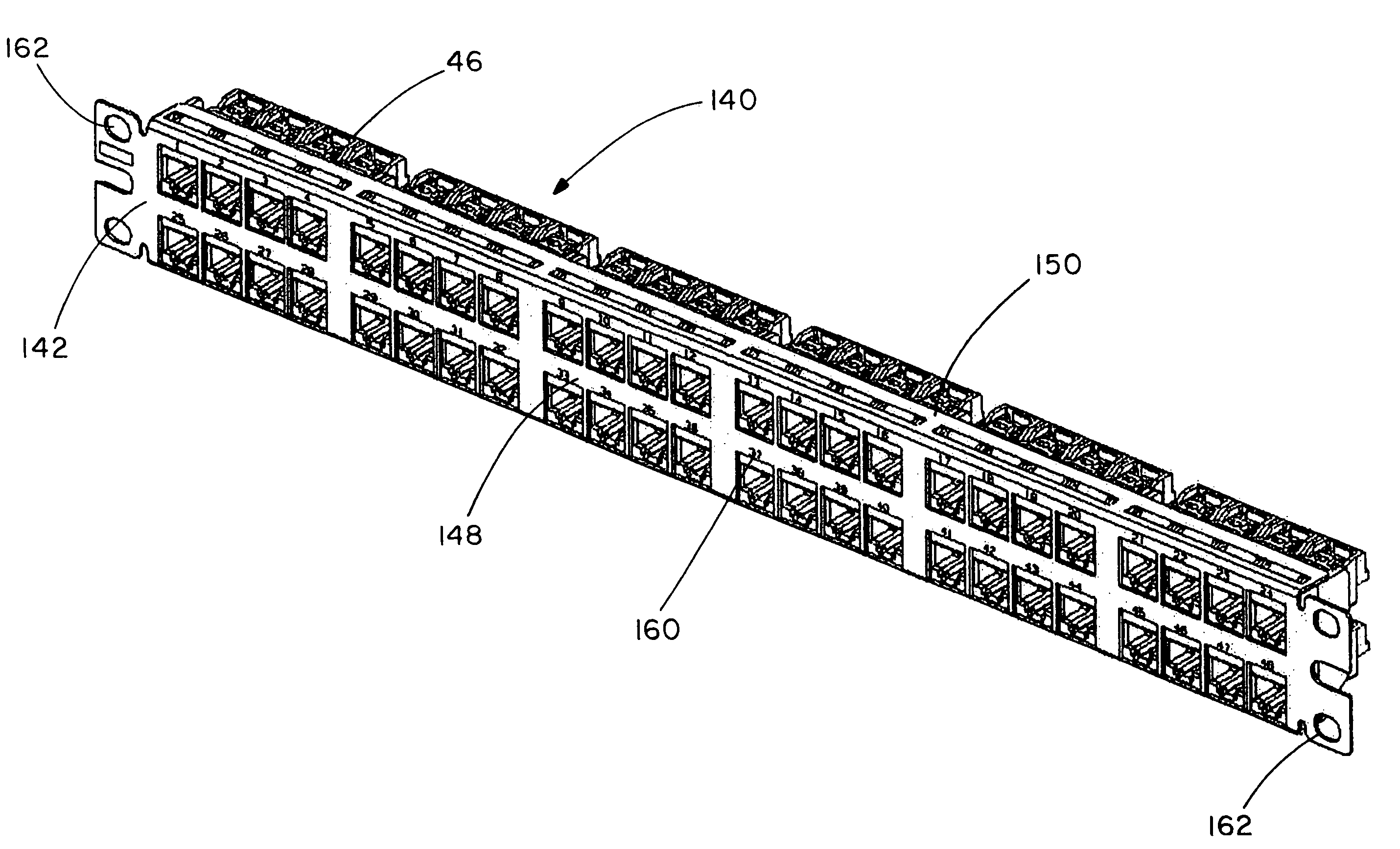
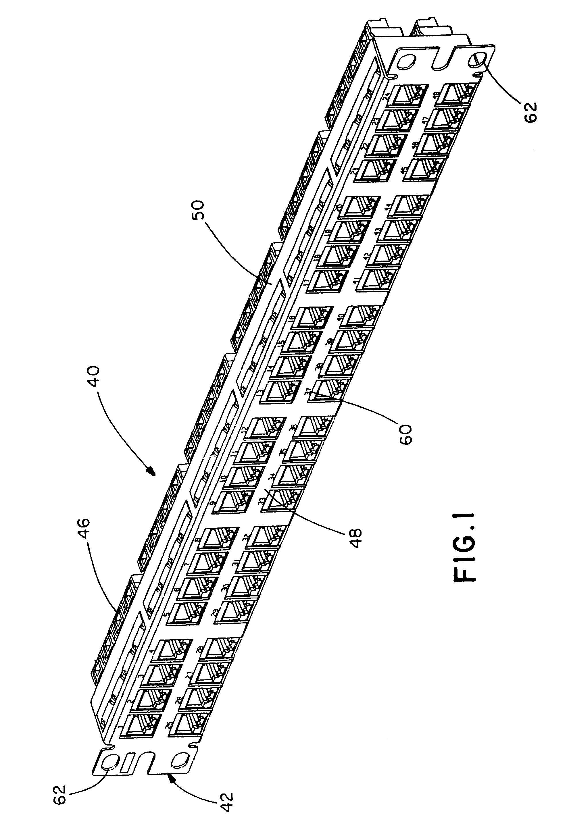
[0047]The illustrated embodiments of the invention are directed to a high density patch panel utilizing six, eight-position faceplates for a total of 48 ports in one rack unit. One rack unit is 1.75 inches high under the EIA / TIA standard. FIGS. 1–19 are directed to patch panel 40, and FIGS. 20–33 are directed to patch panel 140.

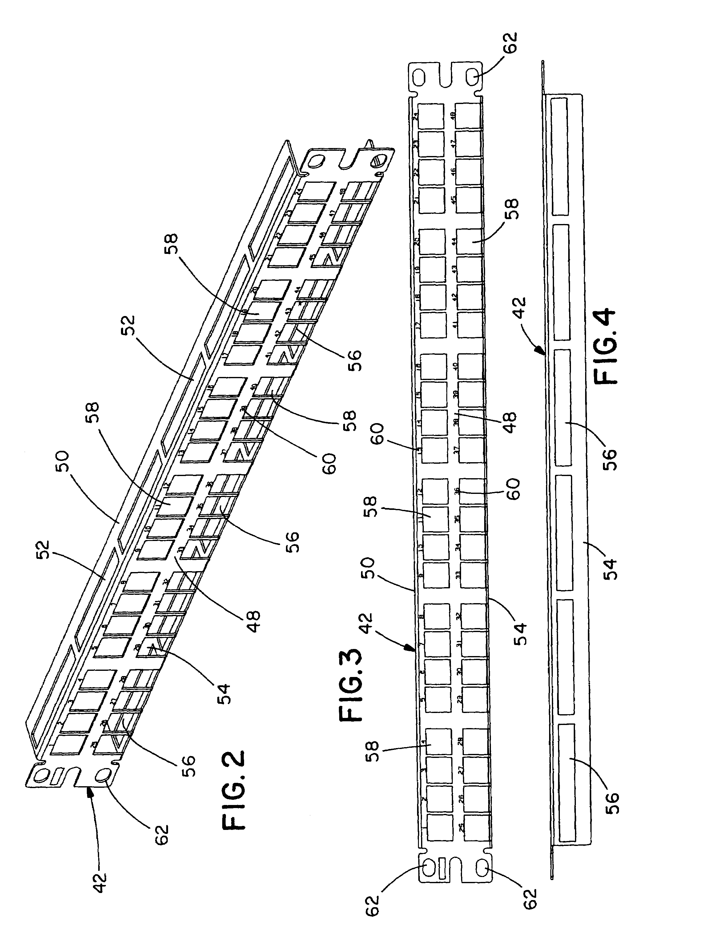
[0048]FIG. 1 shows a fully assembled high density patch panel 40. The patch panel 40 includes a frame 42 (see FIGS. 2–4), a plurality of faceplates, such as faceplate 44 (see FIGS. 5–8), and a plurality of keystone style modular jacks, such as modular jack 46 (see FIGS. 9–12). Preferably, the frame 42 is metal, and the faceplate 44 is plastic. However, it is likewise contemplated that the frame 42 and the faceplate 44 may be made of various materials.

[0049]As can be seen in FIGS. 1–3, the patch panel 40 has six, eight-position faceplates 44. However, it is likewise contemplated that the patch panel 40 may include any number of faceplates having any number of ...


PUM


Abstract

A patch panel is disclosed. The patch panel includes a frame, a faceplate mountable to the frame, and at least one keystone style modular jack mountable into a rear side of the faceplate. The frame has a top flange and a bottom flange, and the frame includes a plurality of openings. The faceplate is mountable to the frame within the top flange and the bottom flange, and the faceplate has a plurality of mounting openings. A method for assembling a patch panel is also disclosed.

Description

CROSS REFERENCE TO RELATED APPLICATIONS[0001]This application claims priority to U.S. Provisional Application Ser. No. 60 / 470,262, filed May 14, 2003, entitled High Density Keystone Jack Patch Panel, and U.S. Provisional Application Ser. No. 60 / 486,682, filed Jul. 11, 2003, entitled High Density Keystone Jack Patch Panel, each of which is incorporated herein by reference.BACKGROUND OF THE INVENTION[0002]The present invention is directed to a patch panel and, more particularly, a high density patch panel for housing a total of 48 keystone style modular jacks in one EIA / TIA rack unit.[0003]Keystone style modular jacks made in accordance with industry standards are well known in the telecommunications industry. Patch panel frames that support keystone style modular jacks in one rack space and that mount to any standard EIA / TIA rack are also known. For example, Hubbell's Premise Wiring UDX Series Jack Panels and Molex's 1U48 Port Power Cat 5e Patch Panel are 48-port panels having frames...

Claims


Application Information

Patent Timeline
IPC IPC(8): H01R13/60H01R13/518H04Q1/14
CPCH01R13/518H04Q1/13H04Q1/09H04Q2201/02H01R24/62
Inventor CAVENEY, JACK E.DONNELL, MARK J.DUCHARME, PAUL B.
Owner PANDUIT
Why Eureka
Try Eureka