Non-orthogonal cable management system

a management system and cable technology, applied in the field of cable management systems, can solve the problems of inaccessible cables in the back of the wire managers, the size of conventional wire managers has reached the cable management system is reaching the limits of the system, so as to achieve space efficient geometry

Inactive Publication Date: 2006-07-04
COMMSCOPE TECH LLC
View PDF10 Cites 117 Cited by
  • Summary
  • Abstract
  • Description
  • Claims
  • Application Information

AI Technical Summary

Problems solved by technology

However, cable management systems are reaching the size limits afforded by certain standards and / or by physical constraints of rooms and environments in which they are mounted.
In addition, conventional wire managers have grown to such a size that cables in the back of the wire managers become inaccessible when behind a large number of other cables.

Method used


Image

  • Non-orthogonal cable management system
  • Non-orthogonal cable management system
  • Non-orthogonal cable management system

Examples


Embodiment Construction

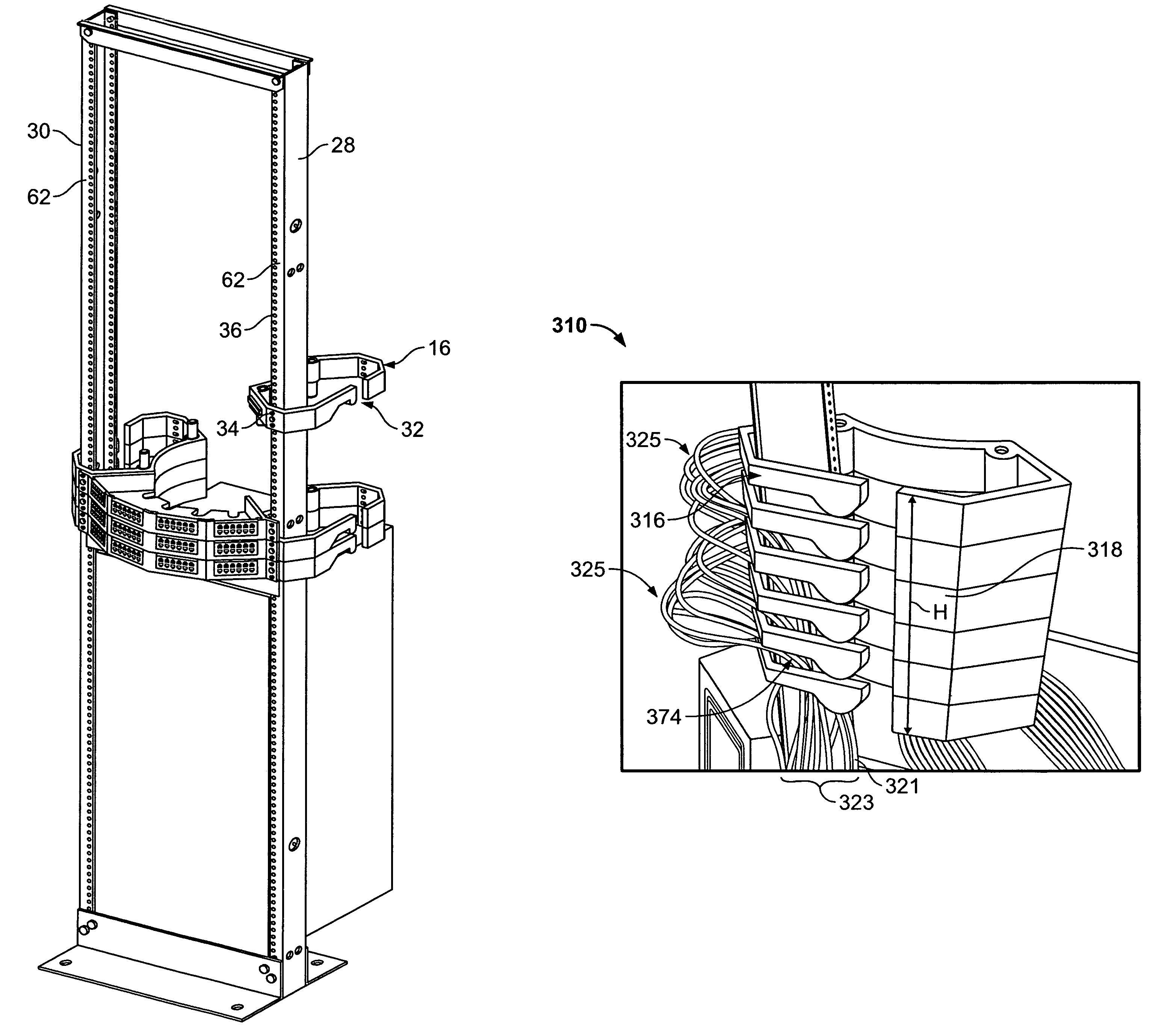
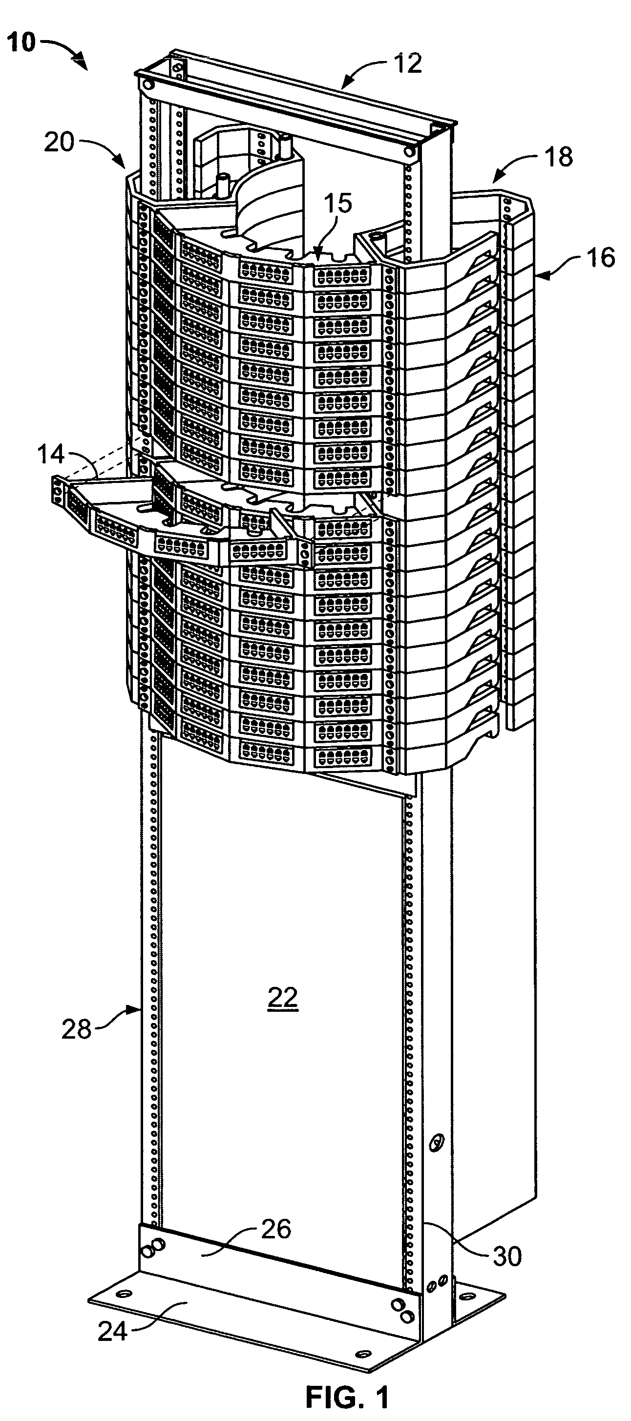
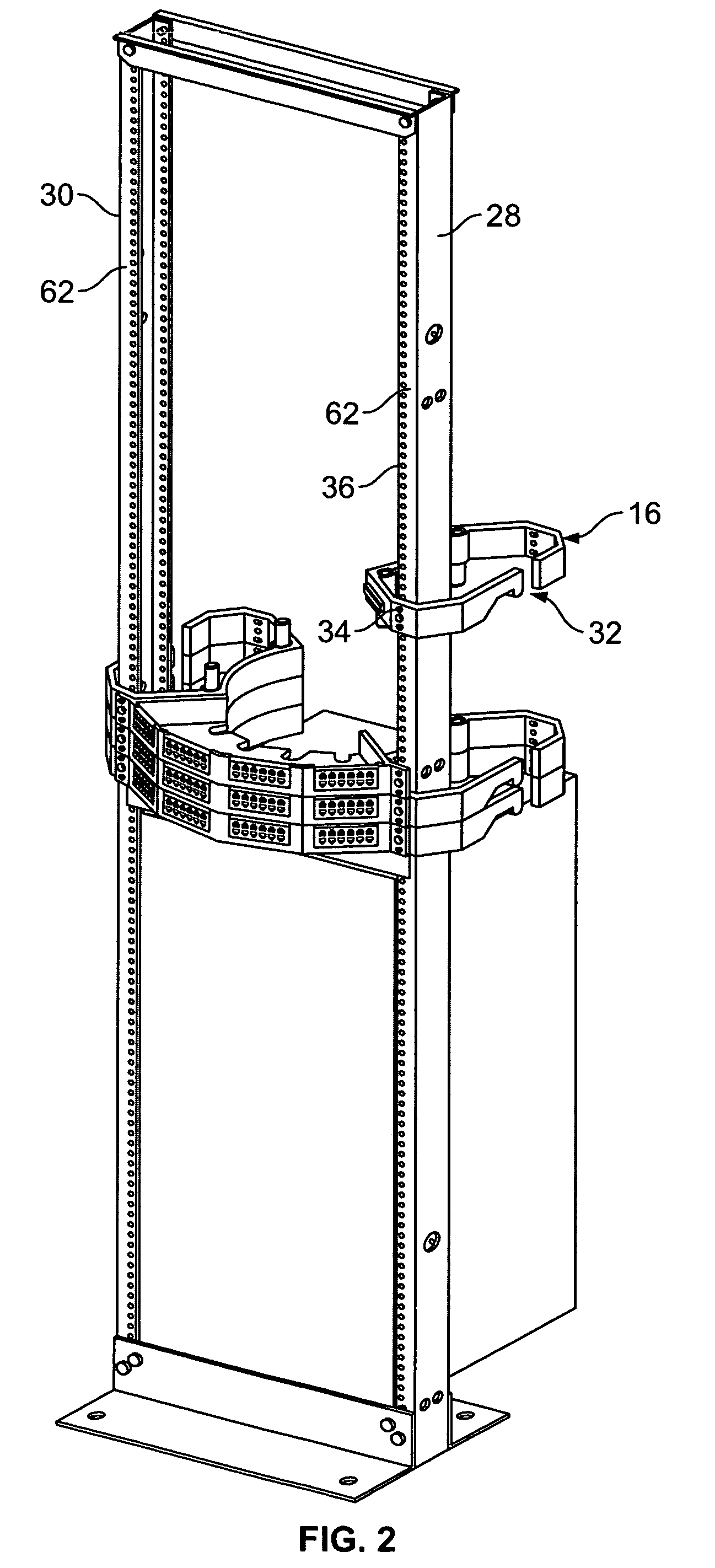
[0035]FIG. 1 illustrates a cable management system 10 formed in accordance with an embodiment of the present invention. The cable management system 10 includes a frame 12 that is configured to be mounted to the floor and / or ceiling of an applications room. A plurality of patch panels 14 are arranged in a manner stacked upon one another forming a distribution assembly 15. The patch panels 14 are securely attached to the frame 12. A plurality of wire managers 16 are also stacked upon one another and arranged in first and second groups on opposite sides of the patch panels 14 forming wire manager modules 18 and 20. The frame 12 extends upward through each of the wire managers 16 and is securely attached to each wire manager 16 and to each patch panel 14 in a manner explained below in more detail. The frame 12 includes a base plate 24 having an upper flange 26 that is joined to support brackets 28 and 30.

[0036]An equipment system 22 (such as a switching network) is also shown in FIG. 1,...


PUM


Abstract

A cable management system is provided having a patch panel and a wire manager. The patch panel has a first connectivity interface configured to connect with electronics cables. The wire manager is located proximate the patch panel and has a body with a curved interior contour. The wire manager is oriented in a non-orthogonal relation to the patch panel such that the body of the wire manager extends rearward at a non-orthogonal angle from the first connectivity interface. Wire managers may be mounted on opposite sides of the patch panel and oriented such that the wire managers and patch panels form a C-shape.

Description

BACKGROUND OF THE INVENTION[0001]The present invention generally relates to a cable management system for interconnecting electronics or fiber optic cables and more specifically to a cable management system having patch panels and wire managers arranged in a non-orthogonal geometry.[0002]Numerous cable management systems exist today and are used in various electronics equipment applications, such as telecommunications, data transmission, networking, video and the like. Typically, to install a cable management system, a rack frame is securely mounted to the floor within the room in which the system is to be maintained. Multiple patch panels or boxes are then secured to the frame in a stacked arrangement. Each patch panel includes multiple connector ports (e.g. RJ45 connector ports) along the front face thereof. Each connector port is adapted to receive a plug on a mating cable that conveys a single data stream, such as for an individual user and the like.[0003]Conventional patch pane...

Claims


Application Information

Patent Timeline
Patent Type & Authority Patents(United States)
IPC IPC(8): H01R9/22G02B6/44H04Q1/14
CPCH04Q1/13G02B6/4452
Inventor DENOVICH, SAMEBERLE, JR., JAMES JOSEPHGREEN, MICHAEL PATRICKHOFFER, JOHN CAREY
Owner COMMSCOPE TECH LLC
Why Eureka
Try Eureka