AI technical title is built by Patsnap AI team. It summarizes the technical point description of the patent document.
a technology of blind signal and components, applied in direction finders using radio waves, instruments, digital computer details, etc., can solve the problems of little volume available in communications devices, the problem of mounting sensors on the outside of communications devices is a problem for users, and the problem of co-channel emitters is expected to only worsen
Inactive Publication Date: 2006-10-17
INTERDIGITAL TECH CORP
View PDF5 Cites 169 Cited by
Summary
Abstract
Description
Claims
Application Information
AI Technical Summary
This helps you quickly interpret patents by identifying the three key elements:
Problems solved by technology
Method used
Benefits of technology
Benefits of technology
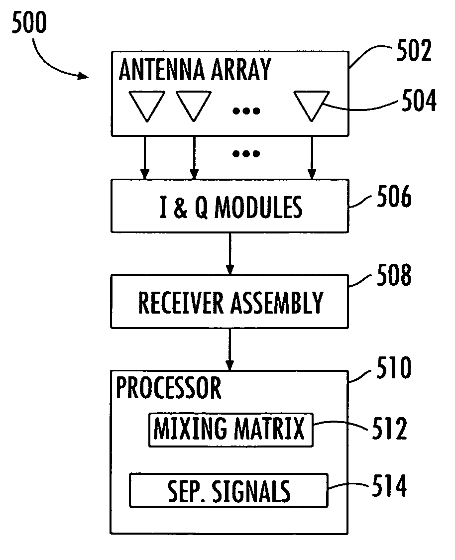
[0013]In particular, signal splitting may be used to further populate the mixing matrix without having to add additional antenna elements in the antenna array. The antenna array may comprise N antenna elements for receiving at least N different summations of the M source signals. A respective in-phase and quadrature module is connected downstream to each antenna element for separating each one of the N different summations of the M source signals received thereby into an in-phase and quadrature component set.
[0020]Another enhancement to the I and Q embodiment involves array deflection for receiving additional sums of signals for use by the mixing matrix without having to add additional antenna elements. Array deflection involves controlling antenna patterns in the azimuth and / or elevation direction.
Problems solved by technology
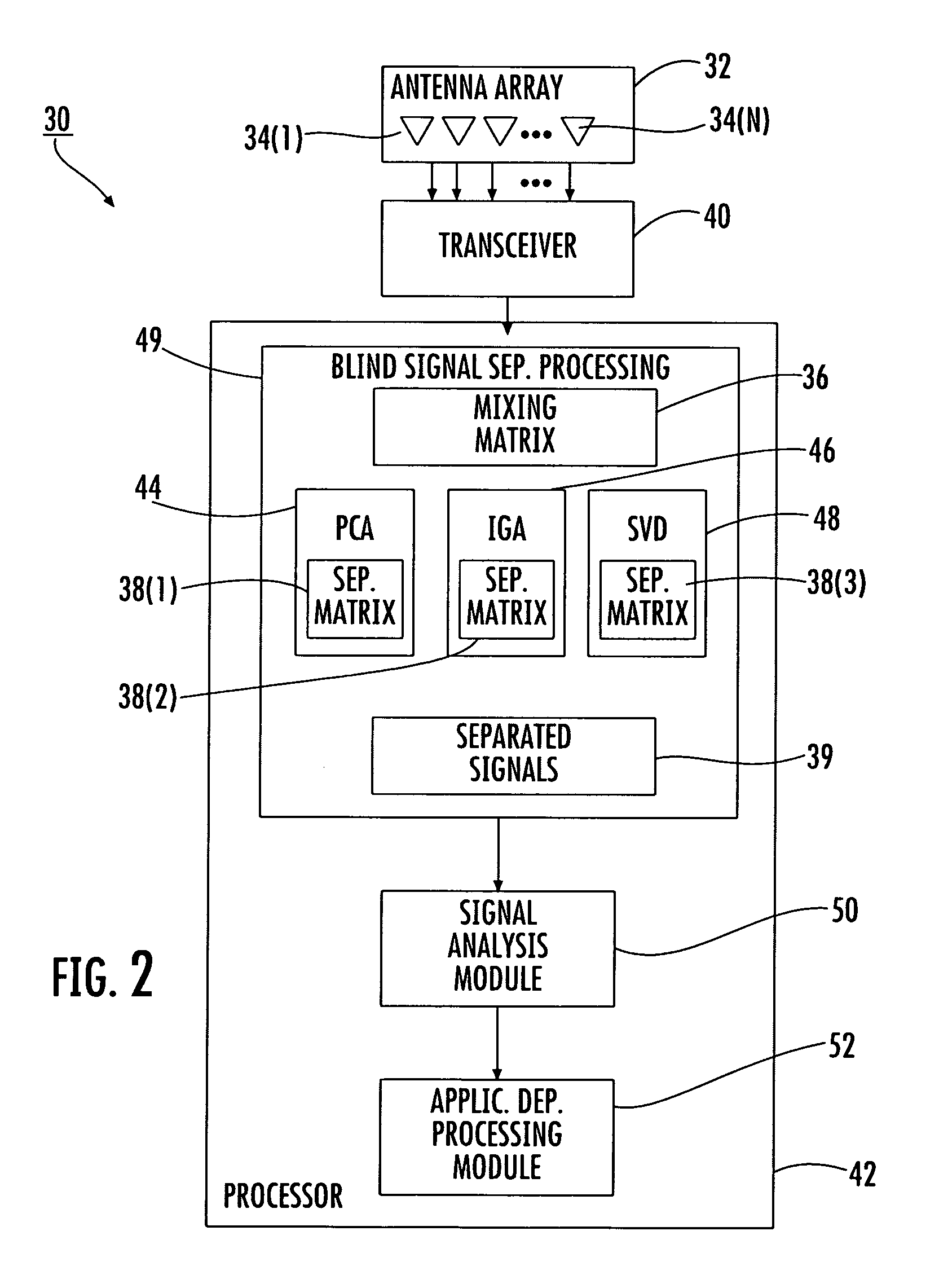
The separation is “blind” because it is often performed with limited information about the signals, the sources of the signals, and the effects that the propagation channel has on the signals.
The problem of co-channel emitters is expected to only worsen in years to come with the development of low power, unlicensed wireless technologies such as Bluetooth and other personal area networks.
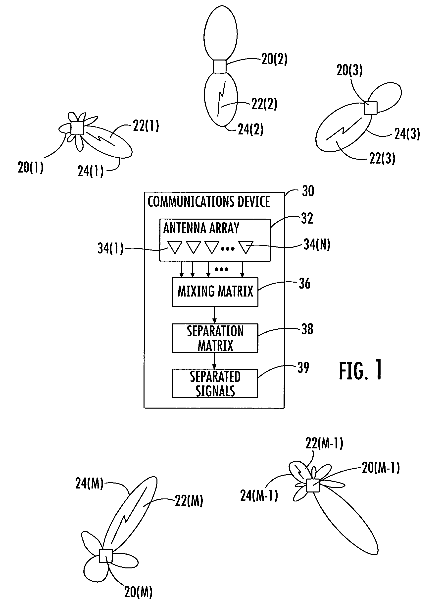
A problem with such an implementation is that as the number of sources M increases, then so does the number of sensors N. Small portable communications devices have little available volume for a large number of sensors N, and mounting the sensors on the outside of the communications devices is a problem for the users.
Method used
Image
Click on the blue label to locate the original text in one second.
Reading with bidirectional positioning of images and text.
Examples
Embodiment Construction
[0050]The present invention will now be described more fully hereinafter with reference to the accompanying drawings, in which preferred embodiments of the invention are shown. This invention may, however, be embodied in many different forms and should not be construed as limited to the embodiments set forth herein. Rather, these embodiments are provided so that this disclosure will be thorough and complete, and will fully convey the scope of the invention to those skilled in the art. Like numbers refer to like elements throughout, and prime notation is used to indicate similar elements in alternative embodiments.
[0051]In communications networks there are source signals intended for a specific communications device, and there are source signals intended for other communications devices operating within the same frequency band. There are also sources of noise which produce signals that are not used for communications, but are received by the communications devices as well.
[0052]To fa...
PUM
Abstract
A communications device for separating source signals provided by M signal sources includes an antenna array comprising N antenna elements for receiving at least N different summations of the M source signals. A respective in-phase and quadrature module is connected downstream to each antenna element for separating each one of the N different summations of the M source signals received thereby into an in-phase and quadrature component set. A blind signal separation processor forms a mixing matrix comprising at least 2N different summations of the M source signals, with each in-phase and quadrature component set providing 2 inputs into the mixing matrix. The mixing matrix has a rank equal up to 2N. The desired source signals are separated from the mixing matrix by the blind signal separation processor.
Description
RELATED APPLICATIONS[0001]This application claims the benefit of U.S. Provisional Application Ser. Nos. 60 / 612,546 filed Sep. 23, 2004; 60 / 612,435 filed Sep. 23, 2004; 60 / 612,433 filed Sep. 23, 2004; 60 / 612,550 filed Sep. 23, 2004; 60 / 612,632 filed Sep. 23, 2004; 60 / 612,548 filed Sep. 23, 2004; 60 / 612,471 filed Sep. 23, 2004; 60 / 612,551 filed Sep. 23, 2004; 60 / 612,469 filed Sep. 23, 2004; 60 / 612,547 filed Sep. 23, 2004; 60 / 615,338 filed Oct. 1, 2004; 60 / 615,260 filed Oct. 1, 2004; 60 / 620,775 filed Oct. 20, 2004; 60 / 620,776 filed Oct. 20, 2004; 60 / 620,862 filed Oct. 20, 2004; 60 / 621,113 filed Oct. 22, 2004; and 60 / 639,223 filed Dec. 23, 2004 the entire contents of which are incorporated herein by reference.FIELD OF THE INVENTION[0002]The present invention relates to the field of signal processing, and more particularly, to separating desired source signals from a mixture of source signals using blind signal separation (BSS) techniques.BACKGROUND OF THE INVENTION[0003]Blind source sep...
Claims
Application Information
Patent Timeline
Application Date:The date an application was filed.
Publication Date:The date a patent or application was officially published.
First Publication Date:The earliest publication date of a patent with the same application number.
Issue Date:Publication date of the patent grant document.
PCT Entry Date:The Entry date of PCT National Phase.
Estimated Expiry Date:The statutory expiry date of a patent right according to the Patent Law, and it is the longest term of protection that the patent right can achieve without the termination of the patent right due to other reasons(Term extension factor has been taken into account ).
Invalid Date:Actual expiry date is based on effective date or publication date of legal transaction data of invalid patent.

