Signal separation using rank deficient matrices

a rank deficient and matrix technology, applied in direction finders using radio waves, multi-channel direction-finding systems using radio waves, instruments, etc., can solve the problems of a large number of small portable communications devices with little available volume for a large number of antennas, and the problem of mounting antennas on the outside of communications devices is a problem for users, so as to achieve narrow solution space

Inactive Publication Date: 2008-02-12
INTERDIGITAL TECH CORP
View PDF17 Cites 11 Cited by
  • Summary
  • Abstract
  • Description
  • Claims
  • Application Information

AI Technical Summary

Benefits of technology

[0019]The signal separation processor also separates from the biased matrix the desired source signal from the plurality of source signals In addition, the above steps may be repeated so that the biased matrix is biased with a new preferred set of parameters. As a result, if the rank deficient processing initially performed on the matrix was not able to determine a unique solution, then parameters associated with the matrix are modified based upon different sets of parameter values, and respective matrix quality factors associated with the different sets of parameter values are determined. The matrix is then biased with the preferred set of parameter values so that the solution space may be narrowed for obtaining a solution.

Problems solved by technology

There are also sources of noise which produce signals that are not used for communications, but are received by the communications devices as well.
However, when the matrix contains more unknown variables than linear equations, the matrix is underdetermined.
However, small portable communications devices have little available volume for a large number of antennas, and mounting the antennas on the outside of the communications devices is a problem for the users.
However, a problem remains that while the number of solutions may be reduced to a finite number or at least a more constrained set, a unique solution may still not be obtained.

Method used


Image

  • Signal separation using rank deficient matrices
  • Signal separation using rank deficient matrices
  • Signal separation using rank deficient matrices

Examples


Embodiment Construction

[0035]The present invention will now be described more fully hereinafter with reference to the accompanying drawings, in which preferred embodiments of the invention are shown. This invention may, however, be embodied in many different forms and should not be construed as limited to the embodiments set forth herein. Rather, these embodiments are provided so that this disclosure will be thorough and complete, and will fully convey the scope of the invention to those skilled in the art. Like numbers refer to like elements throughout, and prime, double prime and triple prime notations are used to indicate similar elements in alternative embodiments.

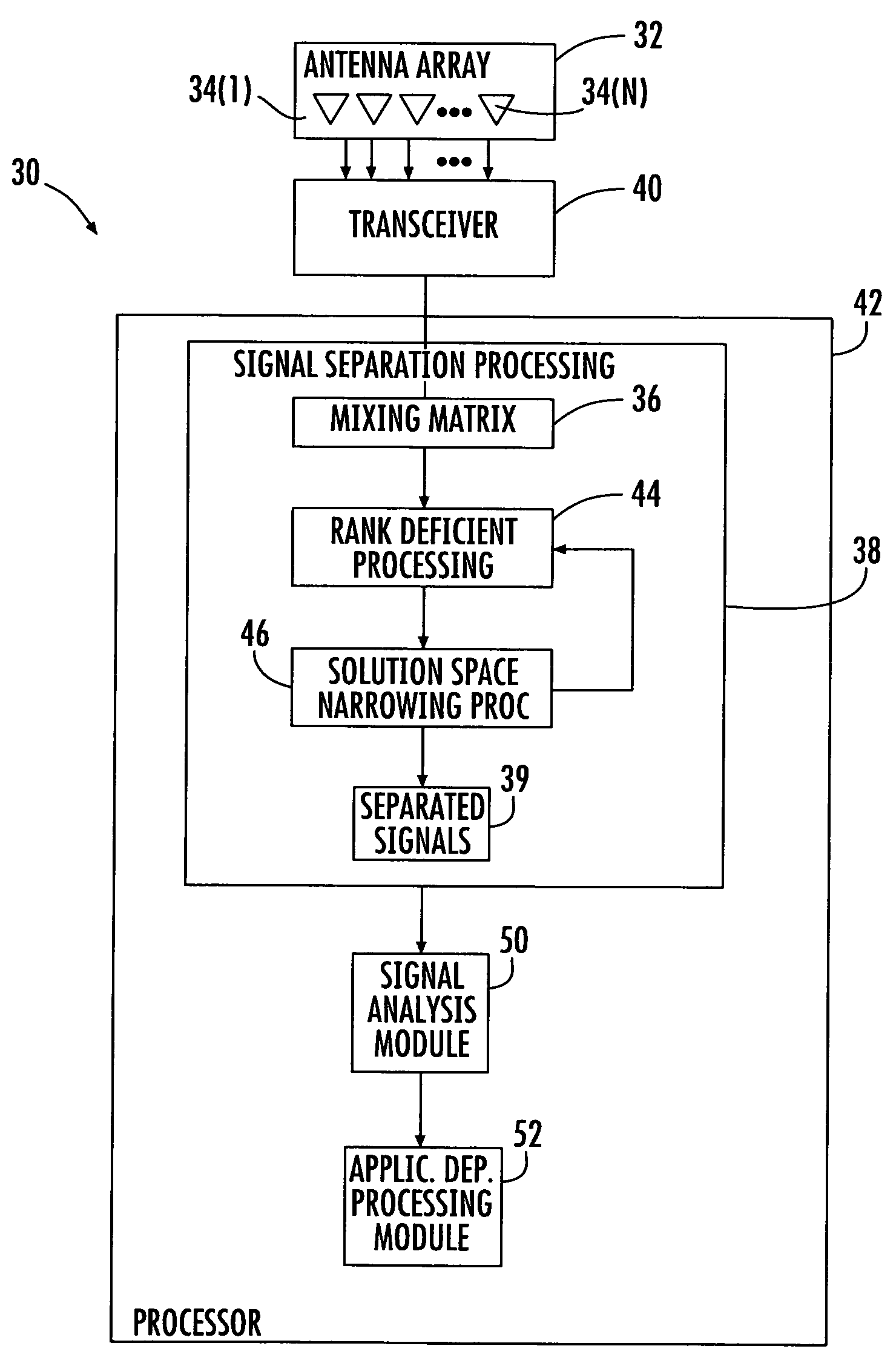
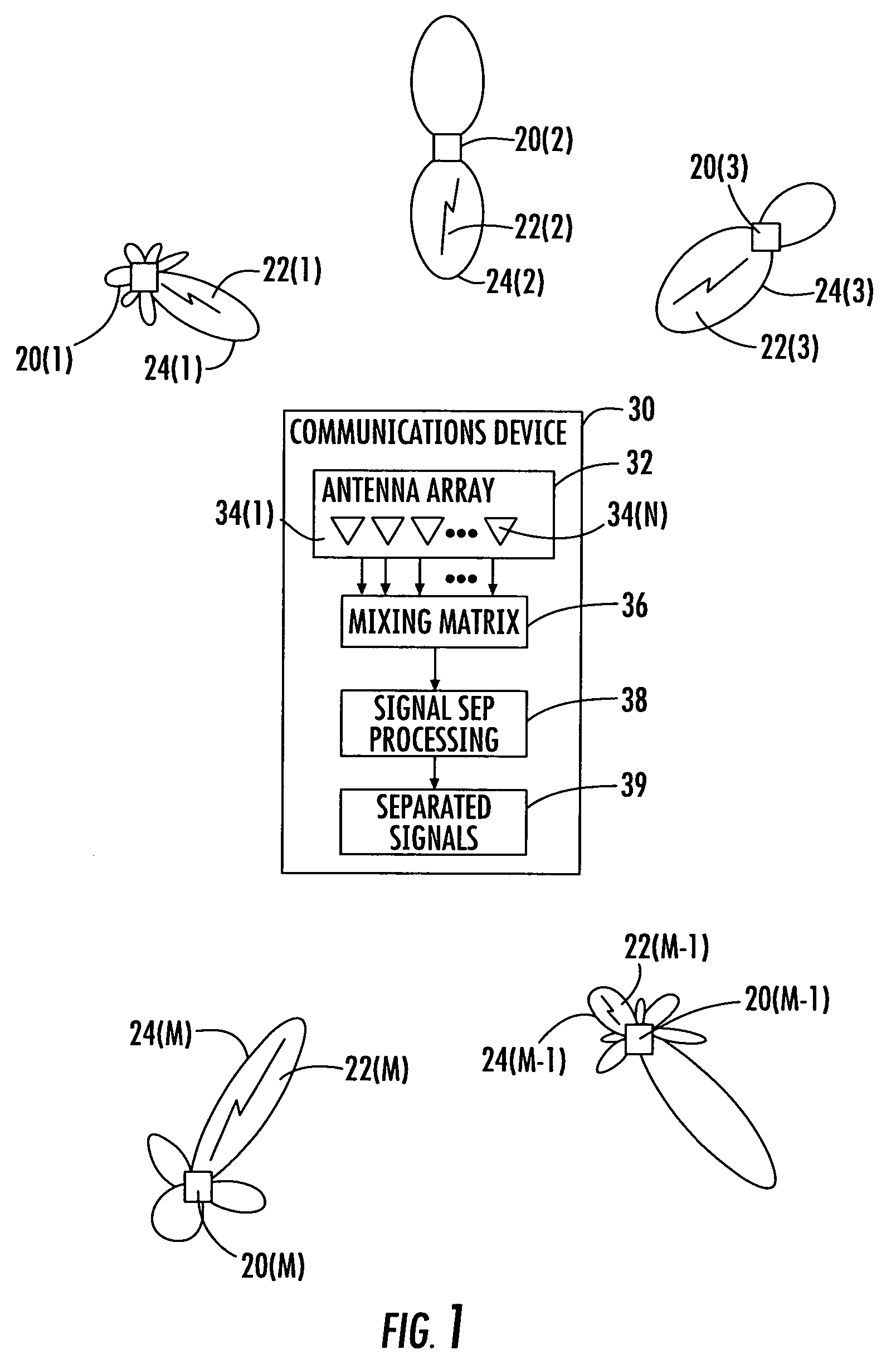
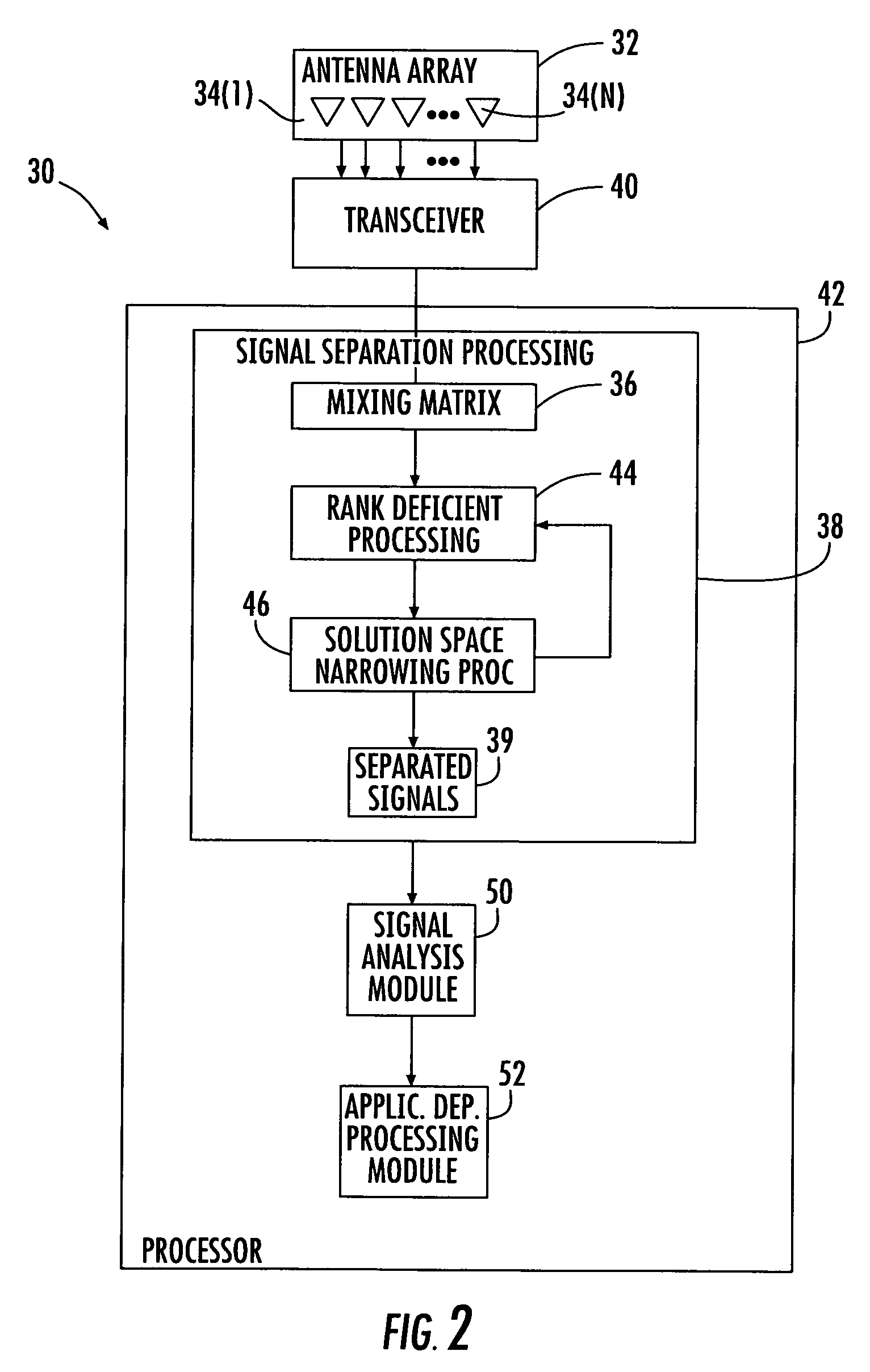
[0036]In communications networks there are source signals intended for a specific communications device, and there are source signals intended for other communications devices operating within the same frequency band. There are also sources of noise which produce signals that are not used for communications, but are received by the communica...


PUM


Abstract

A communications device includes an antenna array for receiving different summations of source signals from a plurality of signal sources, a receiver coupled to the antenna array for receiving the different summations of source signals, and a signal separation processor coupled to the receiver. Processing by the signal separation processor includes creating a matrix based upon the different summations of source signals, with the matrix being defined by linear independent equations with fewer equations than unknowns. The matrix is underdetermined, and parameters associated with the matrix are modified based upon different sets of parameter values, and respective matrix quality factors associated with the different sets of parameter values are determined. The matrix is then biased with a preferred set of parameter values so that the solution space may be narrowed for obtaining a solution.

Description

RELATED APPLICATION[0001]This application claims the benefit of U.S. Provisional Application Ser. No. 60 / 703,609 filed Jul. 29, 2005, the entire contents of which are incorporated herein by reference.FIELD OF THE INVENTION[0002]The present invention relates to the field of signal processing, and more particularly, to separating desired source signals from a mixture of source signals in which rank deficient matrices are formed.BACKGROUND OF THE INVENTION[0003]In communications networks there are source signals intended for a specific communications device, and there are source signals intended for other communications devices operating within the same frequency band. There are also sources of noise which produce signals that are not used for communications, but are received by the communications devices as well.[0004]To facilitate decoding of the source signals of interest, signal separation is used to separate the signals received by a communications device. If the signals can be se...

Claims


Application Information

Patent Timeline
Patent Type & Authority Patents(United States)
IPC IPC(8): G06F19/00G01S3/16G06F15/00
CPCG01S3/74
Inventor GOLDBERG, STEVEN J.SHAH, YOGENDRA
Owner INTERDIGITAL TECH CORP
Why Eureka
Try Eureka