Optical fiber cable with fiber receiving jacket ducts

a technology of optical fiber and receiving jacket, which is applied in the direction of optics, fibre mechanical structures, instruments, etc., can solve the problems of less flexible cable, difficult identification of groups, and inefficient use of space within the cable, so as to reduce the adhesion of fibers to the jacket and the strength of the strength member

Inactive Publication Date: 2006-10-17
PRYSMIAN COMM CABLES & SYST USA LLC
View PDF25 Cites 338 Cited by
  • Summary
  • Abstract
  • Description
  • Claims
  • Application Information

AI Technical Summary

Benefits of technology

[0012]After a study of the requirements for an FTTH cable and the prior art cables, it has been discovered that an FTTH cable having the desired characteristics can be provided by encircling a central strength member with a plastic jacket having a circumferentially continuous outer portion and including slots in the jacket intermediate the outer portion and the strength member which form the major portion of ducts for receiving the optical fibers while also providing that the portion of the jacket between the slots and at the central strength member can be manually readily ruptured or separated from the central strength member.
[0013]The optical fiber cable of the invention is compact and flexible and provides good protection for the fiber or fibers. The optical signal transmission properties of the cable of the invention are good, and the optical fiber or fibers can be quickly and easily accessed. The cable of the invention can be used both indoors and outdoors. The material costs are relatively low and the manufacturing process is relatively simple.

Problems solved by technology

However, when the fiber count is low, e.g. two to twelve fibers, multiple tubes are not desirable, not only for cost reasons, but also because for a given cable size, the space within the cable is not efficiently used.
However, substantial handling of the cable is required to make the fibers available for splicing or connection to other devices, all of the fibers are exposed when the tube is opened which is not desirable if a splice connection to only a single optical fiber is desired, identification of groups is more difficult since the fibers are in one tube and the cable can be less flexible due to the location of the strength members.
Such cables have characteristics similar to the central loose tube cables, but they are difficult to manufacture due to the fact that the optical fibers are fed by fiber pay-offs into the preformed slots.
Such conditions can be especially difficult if the slots are S-Z slots, or alternating direction slots which, as is known in the art, are desirable for mid-span access to the fibers.
One of the problems with the slotted core cable when it is to be used for a cable with only a few optical fibers is that only a small reduction in the diameter of the core can be made.
However, the cable disclosed therein is not satisfactory as an FTTH cable not only because the jacket is bonded to the strength member or is integral with a layer of rubber or plastics encircling the strength member so that the jacket cannot be easily separated manually from the strength member, but also because the location of the fiber receiving compartments cannot be readily determined from externally of the cable.
It is apparent from the foregoing description of prior art cables that the foregoing long distance cables cannot provide the characteristics desired for an FTTH cable.
The use of a central strength member can provide the strength and flexibility requirements, but if provided with the plastic layer of a size needed for a stranded loose tube or slotted core cable, the diameter of the cable is unnecessarily large and excess plastic material is required.

Method used


Image

  • Optical fiber cable with fiber receiving jacket ducts
  • Optical fiber cable with fiber receiving jacket ducts
  • Optical fiber cable with fiber receiving jacket ducts

Examples


Embodiment Construction

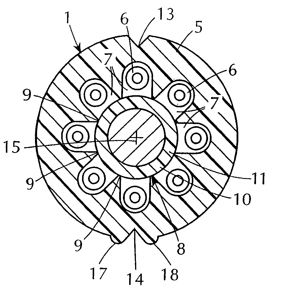
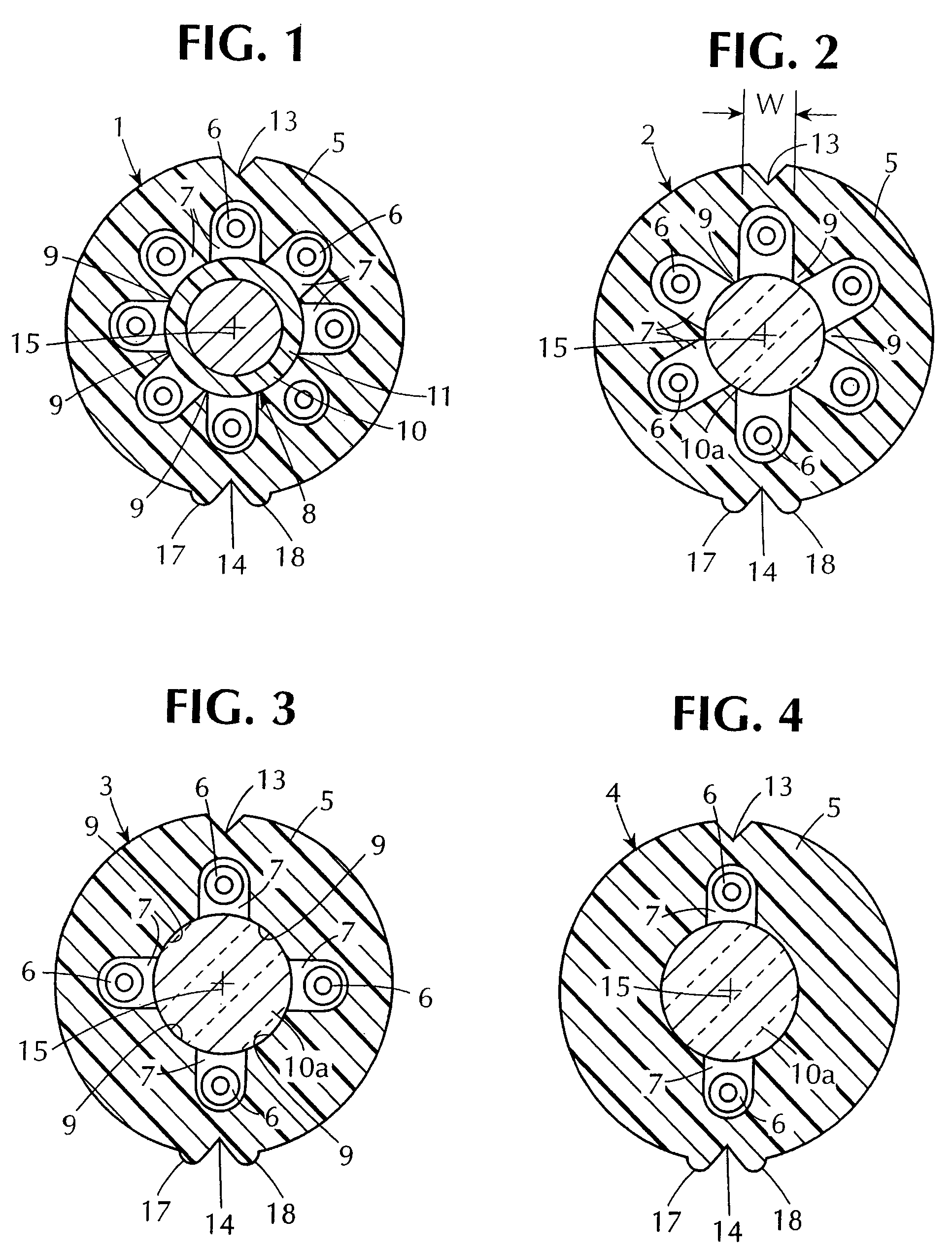
[0032]FIGS. 1–4 illustrate, in cross-section, embodiments of the cable of the invention comprising, respectively, eight, six, four and two optical fibers. The cables can include a greater or lesser number of optical fibers, but normally, will not include more than twelve or less than two optical fibers.

[0033]Each of the cables 1–4 illustrated in FIGS. 1–4 has a tubular jacket 5 made of a plastic conventional in the art, such as polyvinylchloride or polyethylene. Since the cable of the invention can be used indoors as well as outdoors, preferably, the plastic is a plastic which will meet National Electric Code requirements for thickness, and flame propagation and which is low smoke producing. See, for example, cited U.S. Pat. No. 5,390,273.

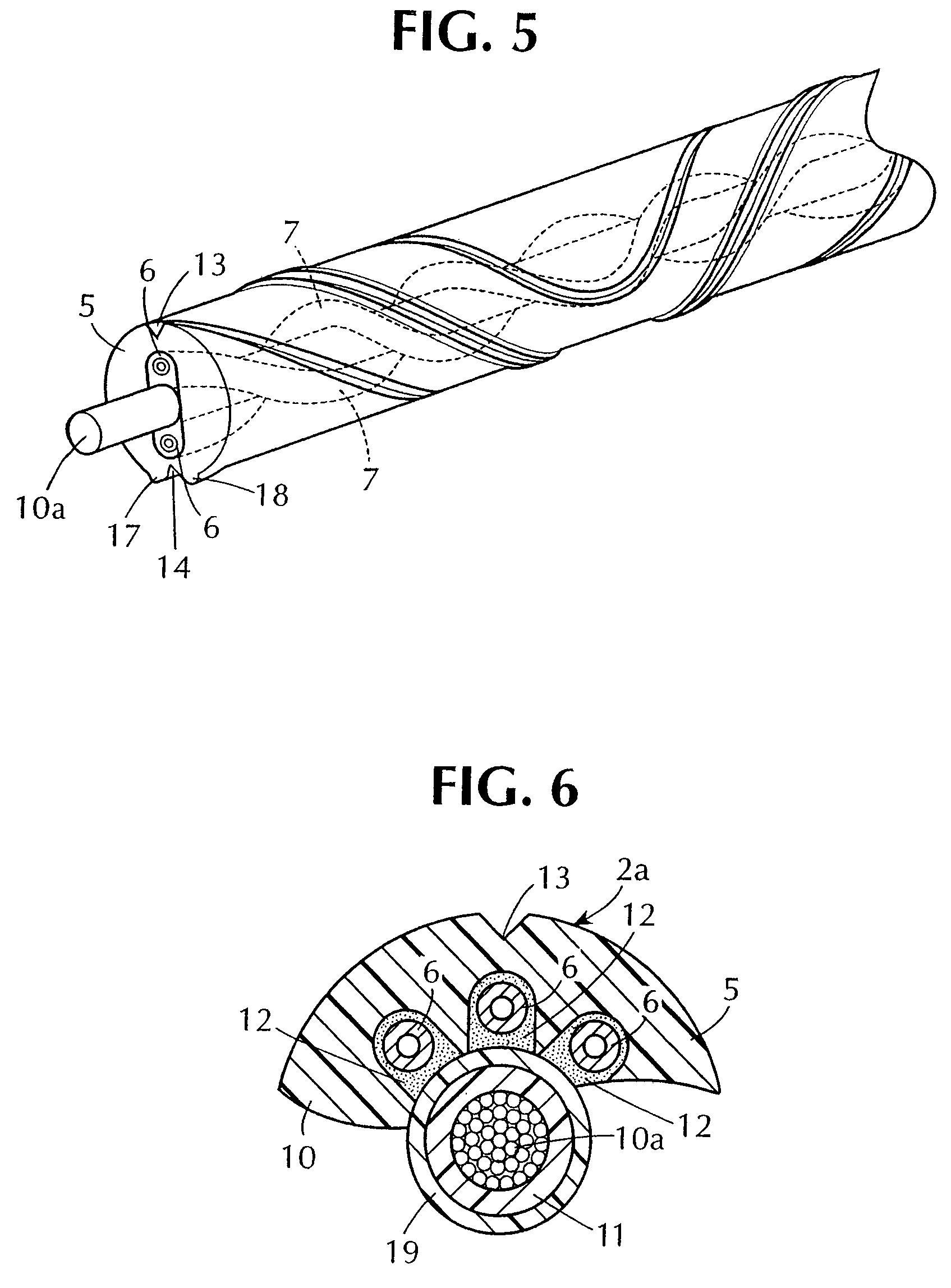
[0034]Preferably, the diameters of the outer surface of the jackets 5 are kept as small as possible consistent with the required protection of the optical fibers and the required size of the jacket slots hereinafter described. For example, the diam...


PUM


Abstract

Optical fiber cables with a central strength member encircled by a jacket having ducts which are disposed around the strength member and which receive one or more optical fibers with jacket material between the ducts and the outer surface of the jacket. The optical fibers are free to move in the ducts, and preferably, the optical fibers are tight buffered. Portions of the jacket intermediate the ducts connect to the strength member which resists longitudinal movement of the jacket relative to the core. However, the jacket can be separated from the core by manual pulling force after the jacket is axially and radially cut at a pair of diametrically opposite ducts. Preferably, the jacket has outer surface indicia showing the positions of the slots, and the cables can include water blocking materials.

Description

[0001]The invention relates to optical fiber cables having a central strength member encircled by a circumferentially continuous jacket or sheath which has therein at least one longitudinally extending chamber or duct which receives an optical fiber or optical fibers, the jacket being manually separable from the strength member.BACKGROUND OF THE INVENTION[0002]Optical fiber cables have been widely deployed mainly as trunk lines and rings around cities. The design of such cables was based on long haul or urban loop requirements and optical fiber counts were high, i.e. 24 to 864 and higher fiber counts. Because long distance applications were most common, emphasis was based upon minimizing signal loss. Other factors considered in the designs were the ease of management of large numbers of fibers during access, splicing and storage. Generally, access to a single fiber was not involved because usually splices were made at the terminations of the cable or the splicing involved the branch...

Claims


Application Information

Patent Timeline
Patent Type & Authority Patents(United States)
IPC IPC(8): G02B6/44
CPCG02B6/4434G02B6/4495G02B6/4431
Inventor FITZ, JON
Owner PRYSMIAN COMM CABLES & SYST USA LLC
Why Eureka
Try Eureka