Apparatus for controlling and metering fluid flow

a fluid flow and apparatus technology, applied in water supply installation, process and machine control, instruments, etc., can solve the problems of ineffective known variable orifice devices, bulky and often expensive arrangements for performing both metering and fluid flow control, and error-free us

Inactive Publication Date: 2006-11-07
RIVATEK
View PDF40 Cites 15 Cited by
  • Summary
  • Abstract
  • Description
  • Claims
  • Application Information

AI Technical Summary

Problems solved by technology

However, if the orifice opening does not retain a consistent shape as the size of the orifice opening is changed, errors result when calculating the flow rate using the above flow equation.
For example, if a circular orifice compresses into a slightly elliptical shape rather than a perfect circular shape, an error may result when calculating the flow rate because the area value for the equation assumes the shape will remain circular.
If the discharge coefficient is not consistent as the size of the orifice opening changes, and if it is not known with precision, errors will again result using the above flow equation.
In either scenario, the separate nature of the metering and controlling functions results in a bulky and often expensive arrangement for performing both metering and control of the fluid flow.
Known variable orifice devices are ineffective for several reasons.
First, known variable orifice devices typically use circular or curved members that are moved with respect to the fluid flow to change the size of the orifice.
Because of the curved nature of these members, the shape of the orifice changes as the size of the orifice changes, which results in significant errors when calculating the fluid flow over a range of orifice sizes.
Second, the changed shape of the orifice leads to non-ideal orifice shapes for at least a portion of the flow range.
This leads to inconsistent flow characteristics for any given opening as flow rate changes, again leading to errors in the calculation of fluid flow.

Method used


Image

  • Apparatus for controlling and metering fluid flow
  • Apparatus for controlling and metering fluid flow
  • Apparatus for controlling and metering fluid flow

Examples


Embodiment Construction

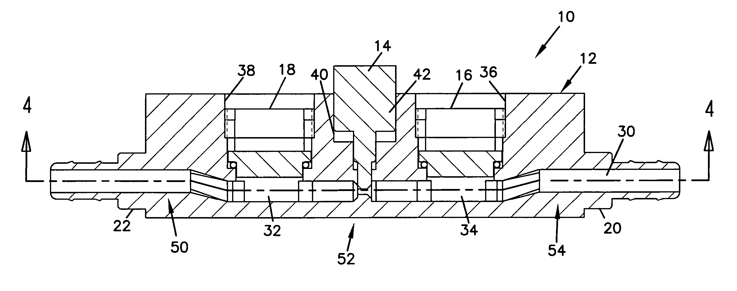
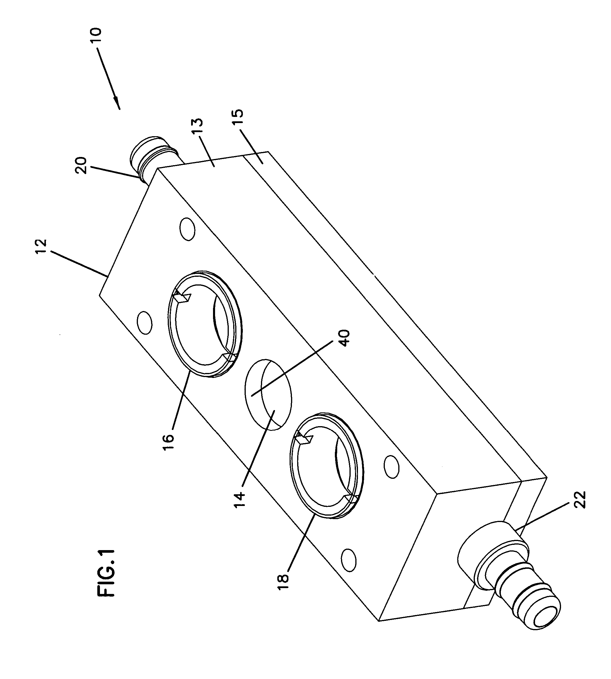
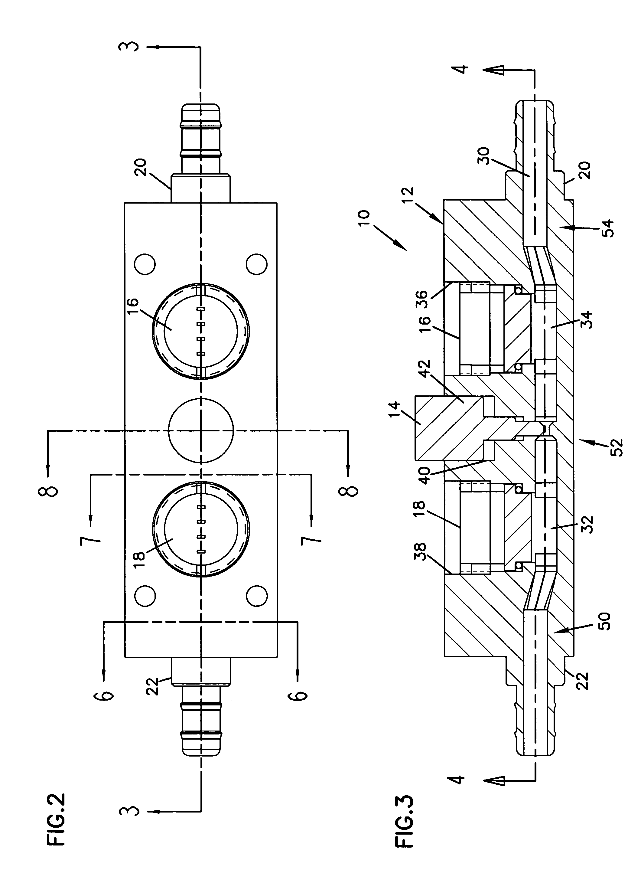
[0037]The invention generally relates to metering and controlling fluid flow, and more particularly to a variable orifice for metering and controlling fluid flow. The variable orifice may be part of a flow device that translates an incoming flow having a circular cross-sectional flow area to a metered flow having a non-circular cross-sectional flow area that includes at least one linear, flat side. One example cross-sectional shape for the metered flow is a rectangle having four linear, flat sides. Other cross-sectional shapes for the metered flow may include, for example, a parallelogram, a rhombus, or other polygon shape, but may also include shapes that have a combination of flat and curved surfaces. The variable orifice may be particularly suited for use in a differential pressure flow meter as will be described herein with reference to the several drawings, although such an application is only exemplary of the many applications to which principles of the present invention may b...


PUM


Abstract

A device for metering and controlling fluid flow includes a variable orifice and is configured to use a pressure sensor. The device includes a fluid flow conduit having at least one planar inner wall that extends along a portion of the fluid flow conduit length, and an element having a linear edge configured to mate with the at least one planar inner wall of the fluid flow conduit. The element is movable in a direction transverse to an axis of the conduit between an open position wherein fluid flows through the conduit and a closed position wherein the element substantially shuts off fluid flow in the conduit.

Description

CROSS REFERENCE TO RELATED APPLICATIONS[0001]This application claims priority to U.S. Provisional Application Ser. No. 60 / 500,774, filed on Sep. 4, 2003, entitled APPARATUS FOR CONTROLLING AND METERING FLUID FLOW, the disclosure of which is incorporated by reference herein in its entirety.BACKGROUND OF THE INVENTION[0002]1. Technical Field[0003]The present invention generally relates to fluid flow, and more particularly to a variable orifice for metering and controlling fluid flow.[0004]2. Related Art[0005]In process control industries, it is common to use small diameter tubes to carry process fluids at low flow rates when small amounts of fluids are required for manufacturing processes. The tubes are almost always of a circular cross-section. Instruments used to measure a flow rate in the tubes must interface with a fluid flowing in the tube while minimizing disturbance to the fluid flow. To minimize disturbance to the fluid flow, the instrument typically includes a circular cross-...

Claims


Application Information

Patent Timeline
Patent Type & Authority Patents(United States)
IPC IPC(8): G05D7/00G01F1/42G05D7/03
CPCG01F1/42G05D7/03Y10T137/0379Y10T137/7759Y10T137/776Y10T137/7761
Inventor NUGENT, DALE ALANKIELB, JOHN ALLANLITECKY, MARK DANIEL
Owner RIVATEK
Why Eureka
Try Eureka