Mold clamping force correction method for mold clamping apparatus

a mold clamping and correction method technology, applied in the field of mold clamping force correction method for mold clamping apparatus, can solve the problems of deterioration in quality, inability to accurately detect mold clamping force, and inability to perform accurate correction of mold clamping force, so as to reduce resetting and fine adjustment, the effect of more accurate and consistent detection

Inactive Publication Date: 2006-11-07
NISSEI PLASTIC IND CO LTD
View PDF8 Cites 5 Cited by
  • Summary
  • Abstract
  • Description
  • Claims
  • Application Information

AI Technical Summary

Benefits of technology

[0010]An object of the present invention is to provide a mold clamping force correction method for a mold clamping apparatus, which method can perform more accurate and consistent (stable) detection as compared with the case where a physical quantity (absolute value) itself is compared with a threshold; more specifically, a mold clamping force correction method for a mold clamping apparatus, which method enables accurate and consistent detection without direct influence of disturbances such as temperature drift and mechanical friction, and which method greatly reduces re-setting and fine adjustment which are necessary when mold closing speed or mold clamping force is changed upon replacement of a mold.
[0011]Another object of the present invention is to provide a mold clamping force correction method for a mold clamping apparatus, which method eliminates the necessity for mold-thickness detection means, such as a scale and a position detector, for directly detecting the thickness of a mold at the time of detection of a mold closure position, to thereby lower cost through reduction in the number of parts, and prevent the structure around a mold from becoming complex.
[0012]Still another object of the present invention is to provide a mold clamping force correction method for a mold clamping apparatus, which method enables accurate detection of a mold closure position while eliminating influences of mold closing speed and other factors, to thereby enable accurate detection of variation in mold closing force and accurate correction of mold clamping force.

Problems solved by technology

Incidentally, unlike a direct-pressure-application-type mold clamping apparatus, because of its operation principle, a toggle-type mold clamping apparatus has a drawback in that slight expansion or contraction of a mold and tie bars, stemming from disturbing factors such as heating temperature of the mold and ambient temperature, causes a considerable variation in mold clamping force, which results in deterioration in quality, in particular at the time of molding of precision products. FIG. 11 shows a variation in mold clamping force Fm with time for the case where the correct value (target value) of mold clamping force Fm is 400 kN.
First, as described above, in a toggle-type mold clamping apparatus, slight expansion or contraction of a mold results in a considerable variation in mold clamping force. Since the conventional mold clamping force control method detects the thickness of a mold (mold clamping force) by use of mold-thickness detection means consisting of a scale supported on a stationary mold plate and a position detector disposed on a movable mold plate; i.e., the method detects slight expansion and contraction, the method cannot accurately detect mold clamping force (mold closure position), and cannot perform accurate correction of mold clamping force.
Second, since the thickness of a mold is detected directly, separate mold-thickness detection means such as a scale and a position detector are needed, leading to an increase in the number of parts, higher cost, and increased degree of complexity of configuration; in particular, an increased degree of complexity of the structure around a mold.

Method used


Image

  • Mold clamping force correction method for mold clamping apparatus
  • Mold clamping force correction method for mold clamping apparatus
  • Mold clamping force correction method for mold clamping apparatus

Examples


Embodiment Construction

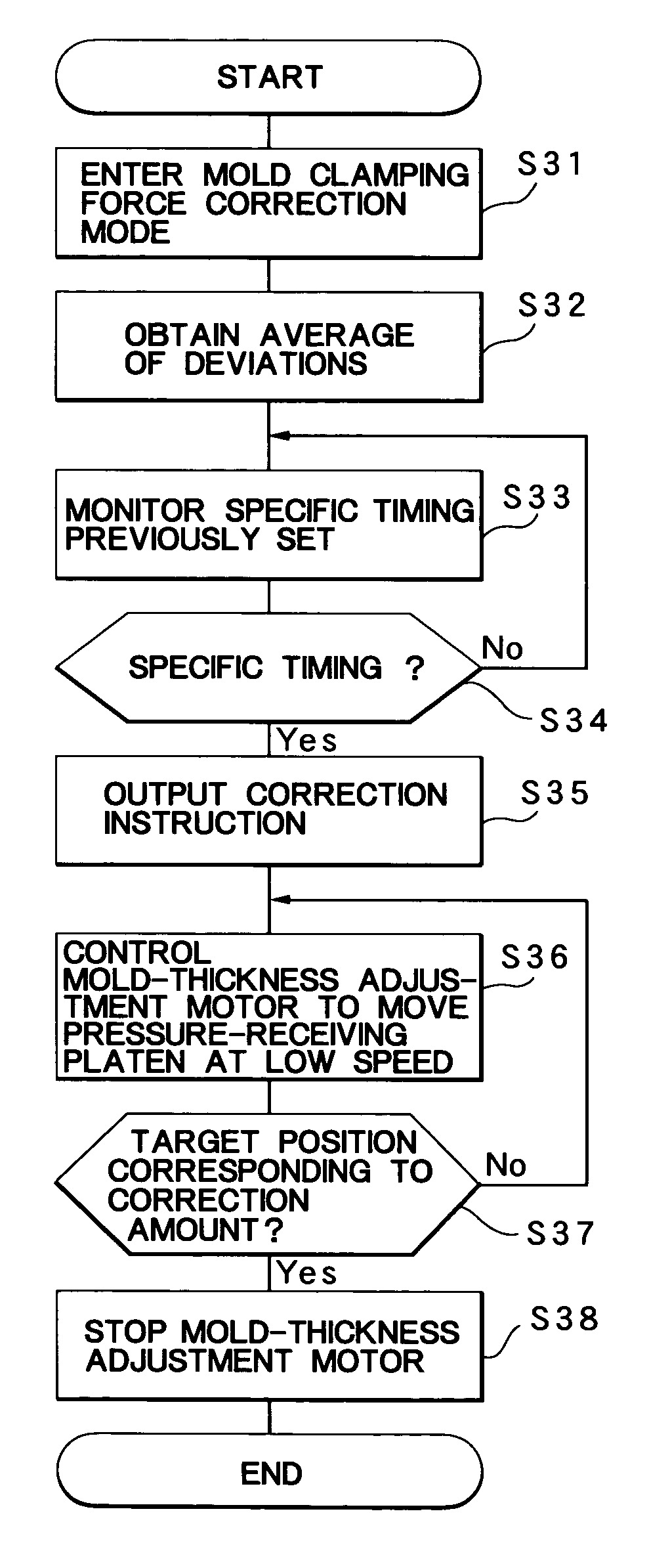
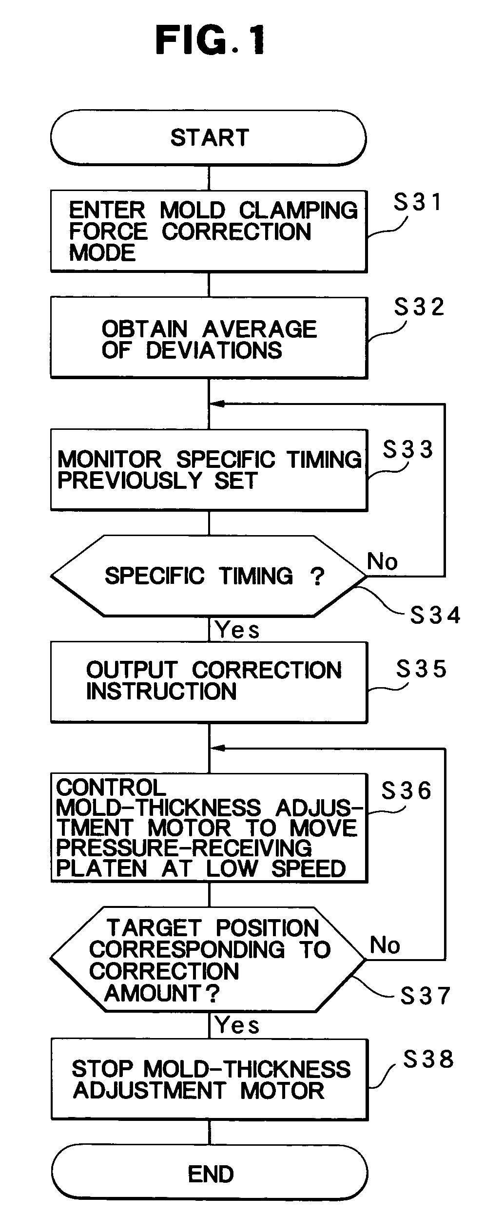
[0025]An embodiment of the present invention will next be described in detail with reference to the drawings. The accompanying drawings are illustrative of the embodiment and are not meant to limit the scope of the invention. In order to describe the invention clearly, detailed description of known parts is omitted.

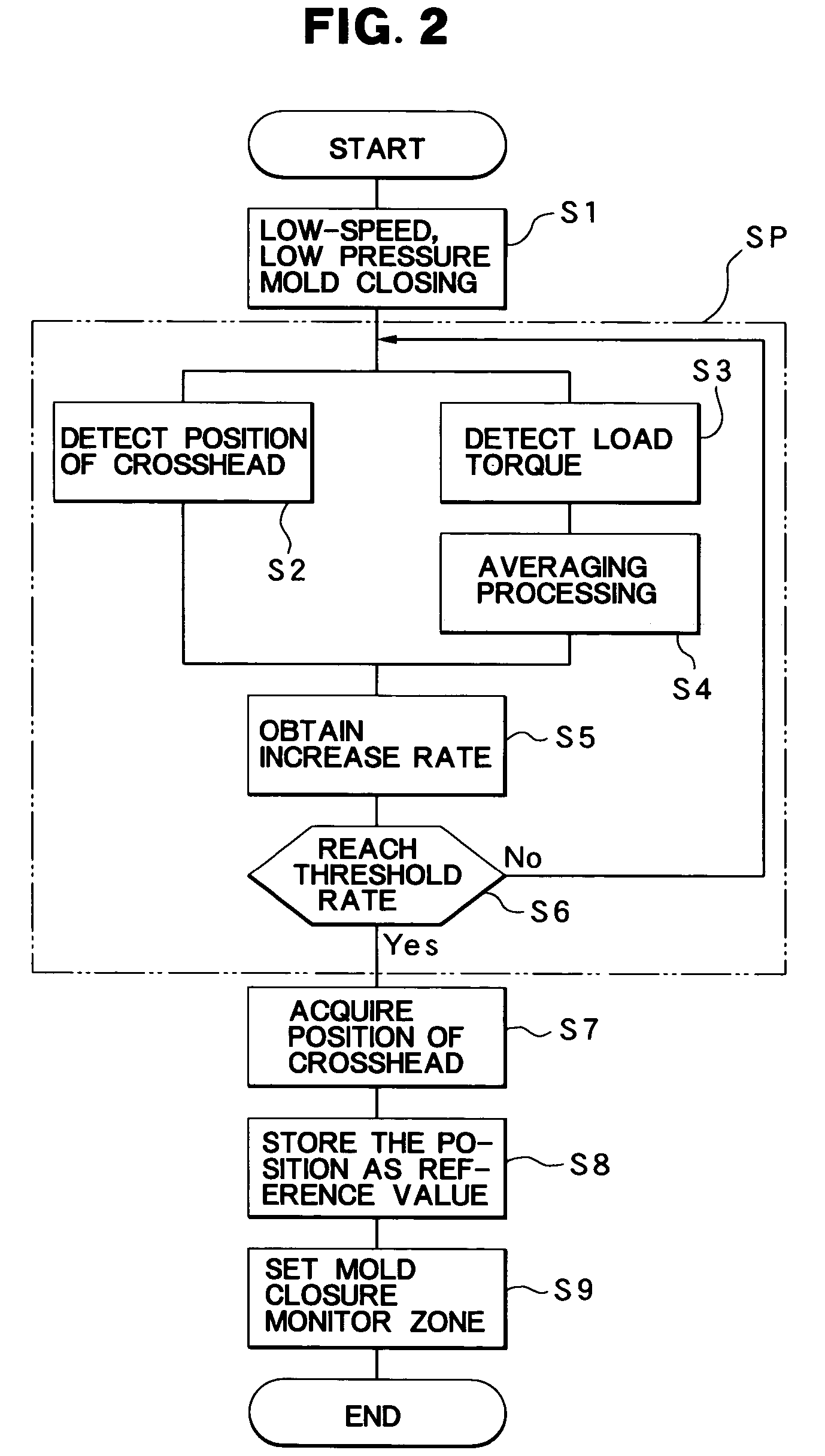
[0026]First, the structure of a toggle-type mold clamping apparatus Mc to which a mold clamping force correction method according to the present embodiment can be applied will be described with reference to FIGS. 5 to 9.

[0027]FIG. 5 shows an injection molding machine M including a toggle-type mold clamping apparatus Mc and an injection apparatus Mi. The toggle-type mold clamping apparatus Mc includes a stationary platen 11 and a pressure-receiving platen 6 which are separated from each other. The stationary platen 11 is fixedly mounted on an unillustrated machine base, and the pressure-receiving platen 6 is mounted on the machine base in such a manner that it can advance ...


PUM

PropertyMeasurementUnit
mold clamping force Fmaaaaaaaaaa
thicknessaaaaaaaaaa

Abstract

A closure position detection mode is provided so as to obtain a rate of variation (which encompasses an amount of variation) in a physical quantity to a predetermined amount of movement of a movable platen or a crosshead, and detect, as a mold closure position, a position when the variation rate reaches a preset ratio. The mold clamping apparatus is previously operated in the closure position detection mode so as to store, as a reference value, the mold closure position at which a target mold clamping force is obtained. In production operation, the mold clamping apparatus is operated in the closure position detection mode so as to obtain an actual mold closure position (detection value). The mold clamping force is corrected on the basis of a deviation of the detection value from the reference value.

Description

BACKGROUND OF THE INVENTION[0001]1. Field of the Invention[0002]The present invention relates to a mold clamping force correction method for a mold clamping apparatus, which method detects the amount of variation (hereinafter simply referred to as “variation”) in mold clamping force during production operation and corrects the mold clamping force on the basis of the detected variation.[0003]2. Description of the Related Art[0004]A conventional toggle-type mold clamping apparatus for clamping a mold of an injection molding machine is disclosed in, for example, Japanese Patent Publication (kokoku) No. 6(1994)-61806. As disclosed in this publication, a toggle-type mold clamping apparatus includes a toggle link mechanism which connects a movable platen for supporting a movable mold half and a crosshead advanced and retracted by a drive unit, and has a function of transmitting pressing force of the crosshead to the movable platen while amplifying the force. In such a mold clamping appara...

Claims


Application Information

Patent Timeline
Patent Type & Authority Patents(United States)
IPC IPC(8): B29C45/64B29C45/80B22D17/26B22D17/20B22D17/32B29C33/20B29C45/66B29C45/76
CPCB29C45/7653B29C45/80B29C2945/76013B29C2945/7602B29C2945/76083B29C2945/7611B29C2945/76167B29C2945/76224B29C2945/76391B29C2945/76505B29C2945/76568B29C2945/76595B29C2945/76943
Inventor HAKODA, TAKASHIKATO, TOSHIMI
Owner NISSEI PLASTIC IND CO LTD
Why Eureka
Try Eureka