Hydroponic growing unit

a growing unit and hydroponic technology, applied in the field of hydroponic growing units, can solve the problems of not being able to change the growing medium, not being able to plant and harvest the produce grown, and not being able to achieve the effect of easy management and efficient planting and harvesting

Inactive Publication Date: 2006-12-05
ROY REJEAN
View PDF22 Cites 49 Cited by
  • Summary
  • Abstract
  • Description
  • Claims
  • Application Information

AI Technical Summary

Benefits of technology

[0006]It is the purpose of the present invention to provide a hydroponic growing unit that grows plants in an efficient and effective manner, and that is easily manageable in planting and harvesting produce grown.
[0008]The growing unit has light means mounted on the base, the light means located in the vertical center of the circular support wall and thus equidistant from each planting block and able to shine on every block within the support wall. Thus all the plants get the same amount of light to grow. The lighting means is also used to circulate and heat air thus heating the environment within the support wall. The growing unit also has watering means for circulating water from the base to the top circular edge of the support wall, then into the top of each planting block, and back to the base from the bottom of each block. Nutrients are added to the water to promote plant growth. Support means are provided for each planting block, the support means used to support each block, from a hook on the support wall, against the inner surface of the wall. The support means makes set-up and take-down of the planting blocks much more simpler and efficient.

Problems solved by technology

The known units work well enough but are not very efficient.
Also the known units do not make it easy to change the growing medium for the plants, the growing medium often inserted into pockets within the support.
Further the known units are not usually equipped with means for facilitating growth such as heat and light.

Method used


Image

  • Hydroponic growing unit
  • Hydroponic growing unit
  • Hydroponic growing unit

Examples


Embodiment Construction

[0022]For the sake of clarity, all the elements of the hydroponic growing unit are not shown in all the views one would normally expect them to appear in. For example, the watering system to be described is not shown in all the views where one would expect to see it.

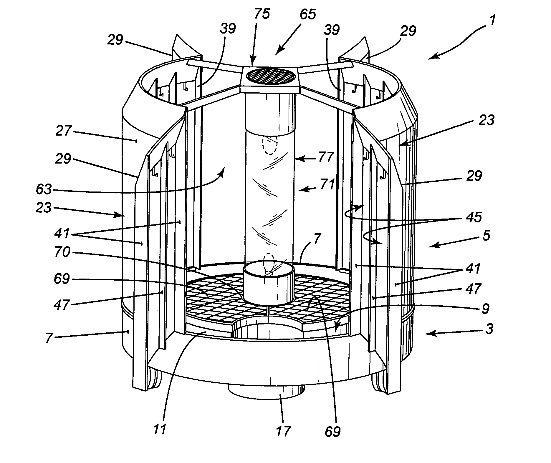
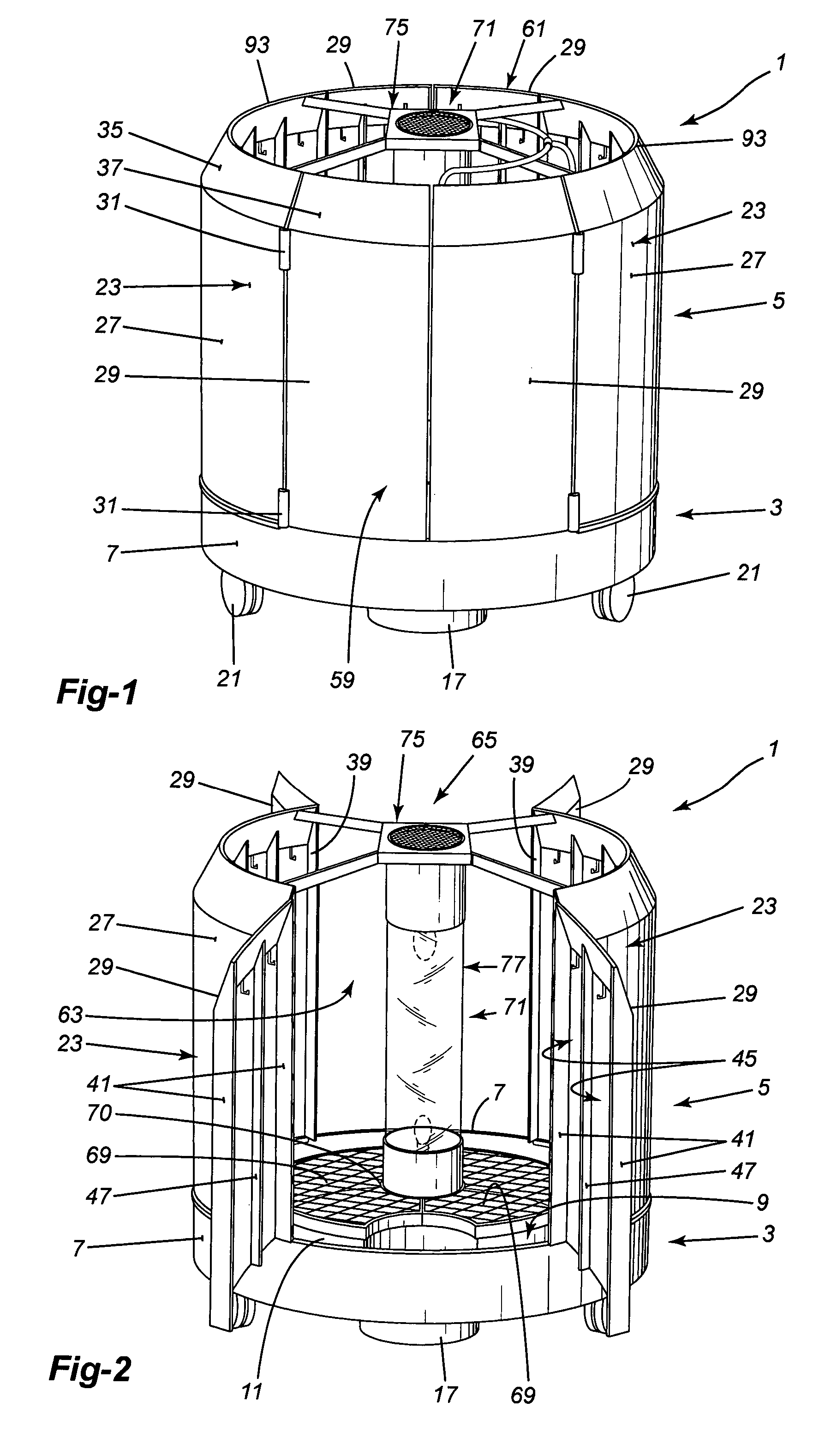
[0023]The hydroponic growing unit 1, as shown in FIGS. 1 and 2, has a base 3 and a support wall 5 mounted on the base 3. The base 3 is relatively short in height compared to the height of the support wall 5 and is generally circular in shape when viewed from the top. The base 3 is shaped to have an outer vertical side wall 7 defining the circular periphery of the base, and is also shaped to form a container to hold liquid.

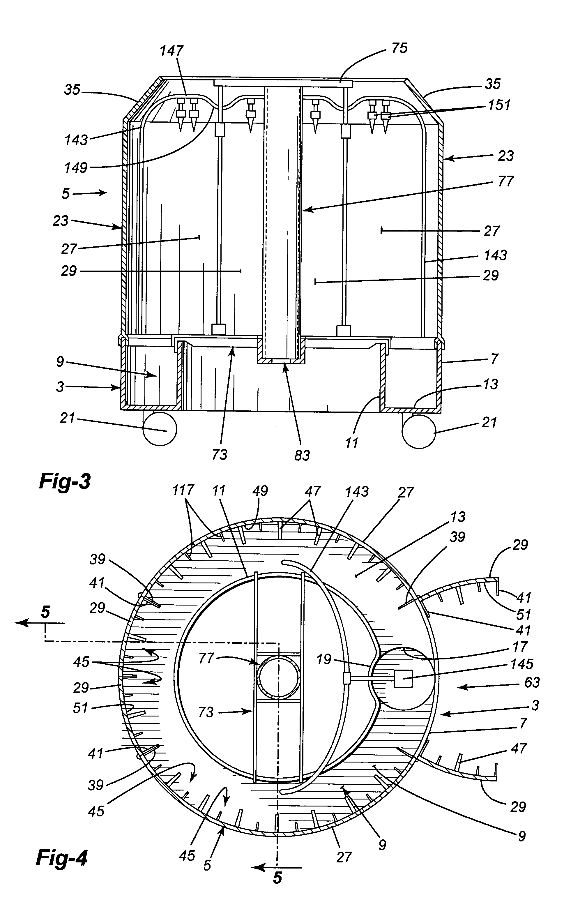
[0024]In its preferred form, the base 3 is in the shape of an annular trough 9, as shown in FIG. 3, the trough having outer and inner circular, vertical, side walls 7, 11 joined by a bottom wall 13. The trough 9 has a generally circular depression or well 17 formed in the bottom wall 13 in which a pump ...


PUM


Abstract

A hydroponic growing unit having a base shaped to hold liquid, the outer periphery of the base defined by an outer, vertical base wall. The unit has a vertical plant support wall forming a generally annular enclosure, the support wall mounted on the wall of the base to extend above the base and to enclose space above the base. There is at least one opening in the support wall providing access to the enclosed space and to the inner surface of the support wall. The opening is normally closed by at least one wall panel forming part of the support wall. The unit has vertical light means mounted in the center of the annular enclosure. Planting block support means are arranged on the inner surface of the support wall near the top and planting blocks, in which plants are planted, are mounted on the support means in a circle to have the plants face the central light means. A watering member is associated with each support means to provide water, pumped from the base, to the top of each block mounted on the support means.

Description

BACKGROUND OF THE INVENTION[0001]1. Field of the Invention[0002]This invention is directed toward a hydroponic growing unit. The invention is more particularly directed toward a hydroponic growing unit having a circular, vertical, support wall mounted on a base, the support wall providing support for plants being grown on the inner surface of the support, the base holding liquid for the plants.[0003]2. Description of the Related Art[0004]Hydroponic gardening units are well known. Most of the known units have one or more vertical plant support means mounted on a container or tray which tray holds a liquid for the plants on the support means. the liquid is normally a mixture of water and nutrients. The liquid is pumped from the tray up to the top of the support means from where it trickles down thorough plants growing on the support means back into the tray for recirculation.[0005]The known units work well enough but are not very efficient. Many of the units have only a single column ...

Claims


Application Information

Patent Timeline
Patent Type & Authority Patents(United States)
IPC IPC(8): A01G31/06A01G31/02
CPCA01G31/02Y02P60/21
Inventor ROY, REJEAN
Owner ROY REJEAN
Why Eureka
Try Eureka