Breakaway hinge system for appliance door

Inactive Publication Date: 2006-12-19
MANSFIELD ENGINEERED COMPONENTS
View PDF6 Cites 31 Cited by
  • Summary
  • Abstract
  • Description
  • Claims
  • Application Information

AI Technical Summary

Problems solved by technology

Damage to appliances and the hinges and doors thereof commonly occurs when the door is moved beyond its intended full-open position by placement of excessive weight on the door or by manual force through in

Method used


Image

  • Breakaway hinge system for appliance door
  • Breakaway hinge system for appliance door
  • Breakaway hinge system for appliance door

Examples


Embodiment Construction

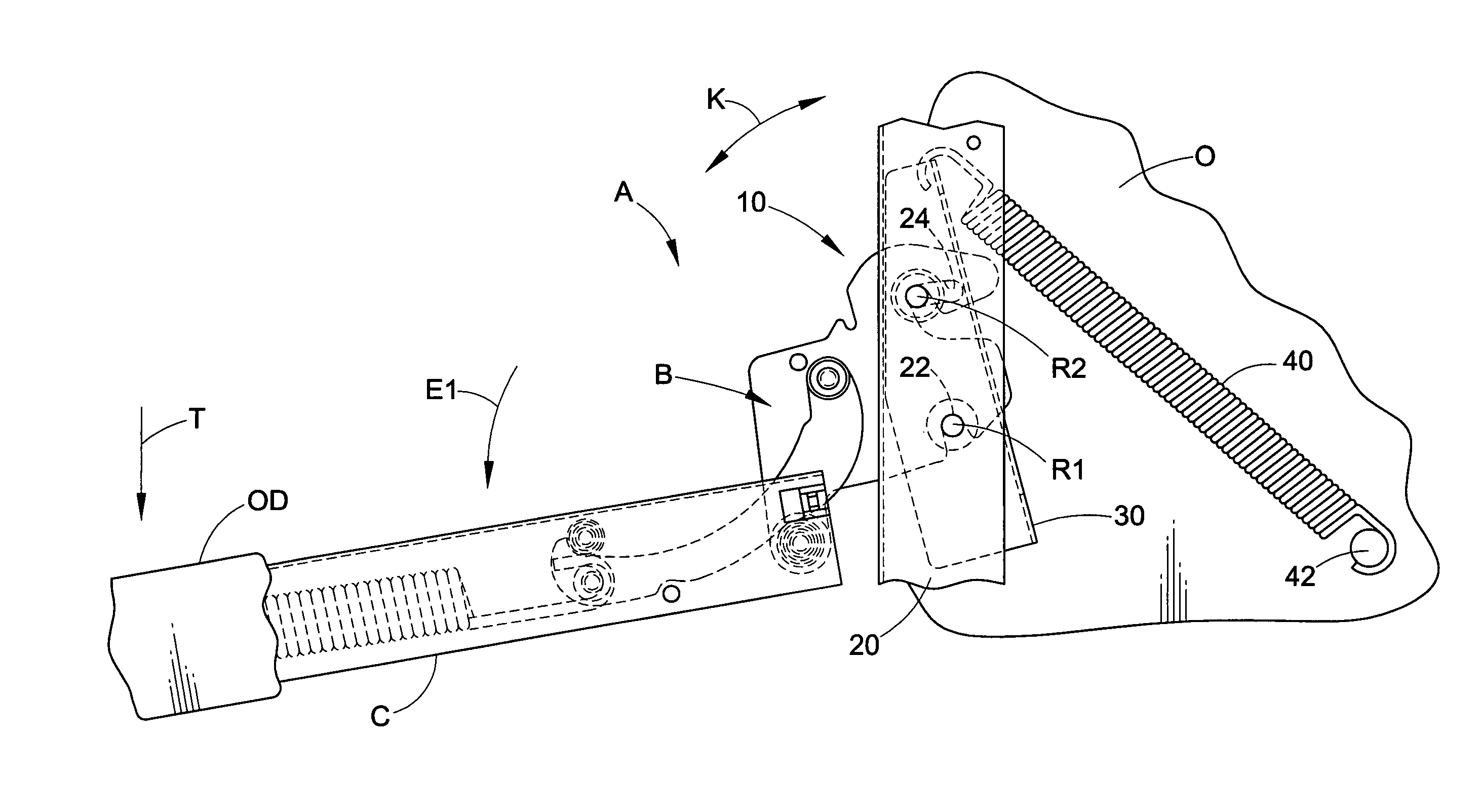
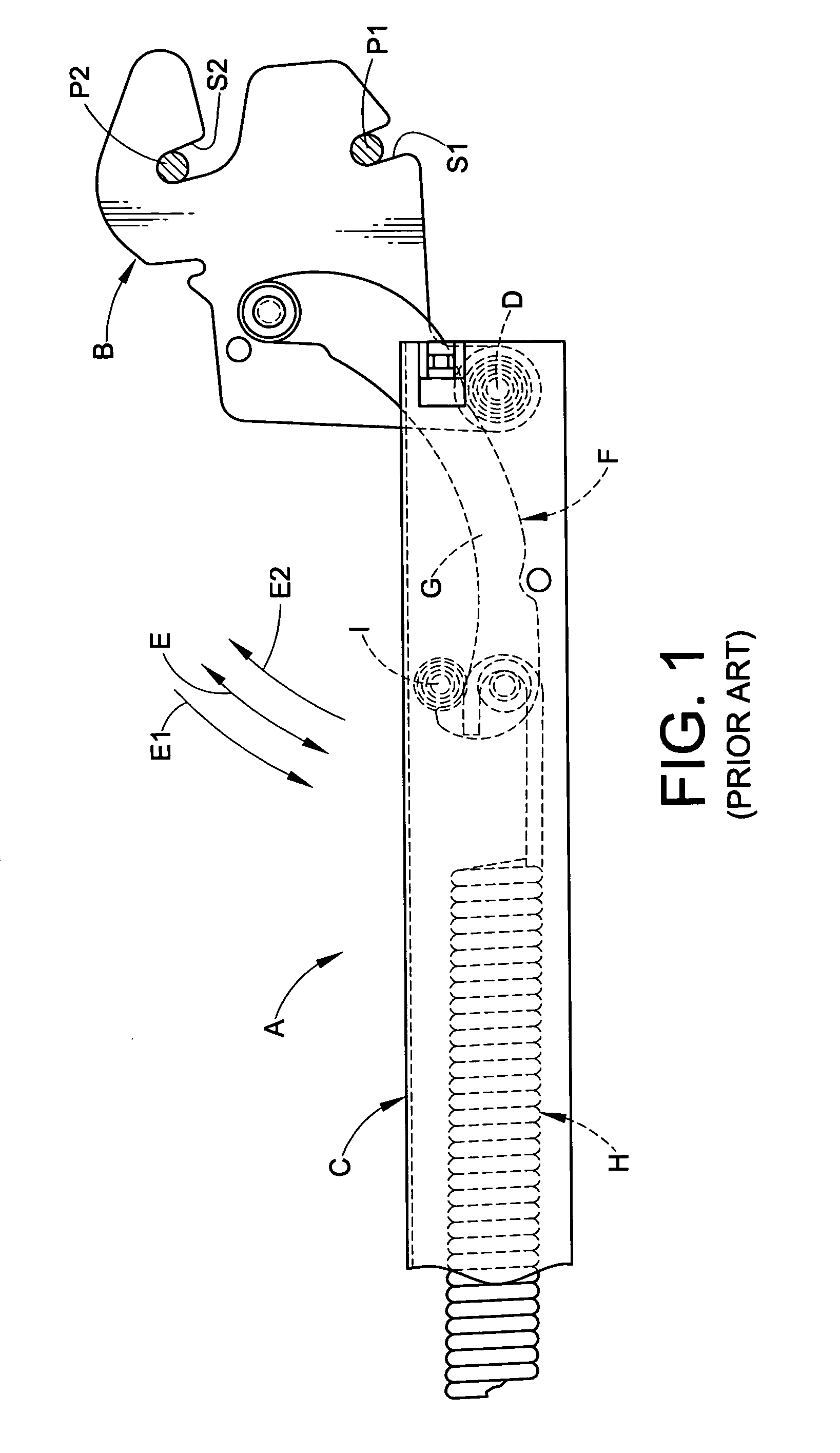
[0016]FIG. 1 illustrates a conventional hinge assembly A that includes a claw B adapted for connection to a frame or chassis of an appliance such as a oven or any other appliance via first and second pins P1,P2 that are connected to the appliance frame. The hinge assembly A further comprises a channel member C (typically a U-shaped or C-shaped member) having a first end pivotally connected to the claw B at a pivot point D so that the channel is adapted for movement on an arc E relative to the claw B. Typically, the channel C is connected to an appliance door such as an oven door that closes an access opening of the appliance.

[0017]The claw B and the channel C are also operably interconnected through a link assembly F. The link assembly F comprises one or more link members G that are pivotally connected at their first ends to the claw B. The one or more link members G are connected at an opposite, second end to the first end of a coil spring H by way of a transversely extending rivet...


PUM


Abstract

A breakaway hinge system for an appliance door includes a claw and a receptacle adapted to receive and retain the claw. The receptacle includes a support member and at least one hinge mounting structure that is engaged by the claw. The at least one hinge mounting structure is movable relative to the support member between first and second positions. A spring biases the at least one hinge mounting structure to the first operative position, and the at least one hinge mounting structure is movable to the second position in response to application of force to the hinge assembly having a magnitude sufficient to overcome the spring. The at least one hinge mounting structure can be a pin or like structure provided as part of a pair of pins connected directly or indirectly to the support member.

Description

BACKGROUND OF THE INVENTION[0001]Damage to appliances and the hinges and doors thereof commonly occurs when the door is moved beyond its intended full-open position by placement of excessive weight on the door or by manual force through inappropriate use. Another drawback to attempted movement of an appliance door beyond its intended full-open position during improper use of the appliance is the possibility that the appliance can tip forward.[0002]In light of the foregoing, a need has been identified for a breakaway hinge system for appliance doors that prevents or at least reduces the likelihood of damage to the appliance, its door and hinges upon movement or attempted movement of the door beyond its full-open position.SUMMARY OF THE INVENTION[0003]In accordance with a first aspect of the invention, a receptacle for mounting a hinge assembly includes a support member and a second member movably connected to the support member. The second member is movable relative to said support m...

Claims


Application Information

Patent Timeline
IPC IPC(8): E05F1/08E05D3/02E05F1/12F24C15/02
CPCE05D3/022E05F1/1276F24C15/023E05Y2201/47E05Y2600/13Y10T16/53885E05Y2900/308Y10T16/53834Y10T16/522E05Y2900/30E05F5/06E05Y2800/424E05F5/08
Inventor COLLENE, JAMES J.HABEGGER, JEFFREY D.
Owner MANSFIELD ENGINEERED COMPONENTS
Why Eureka
Try Eureka