Powered remote release actuator for a seat assembly
a remote release actuator and seat technology, applied in the field of seat assemblies, can solve the problems of requiring a plurality of actuation handles extending from the seatback, seat bottom, or other vehicle structure, and conventional remote actuation devices suffer
- Summary
- Abstract
- Description
- Claims
- Application Information
AI Technical Summary
Benefits of technology
Problems solved by technology
Method used
Image
Examples
second embodiment
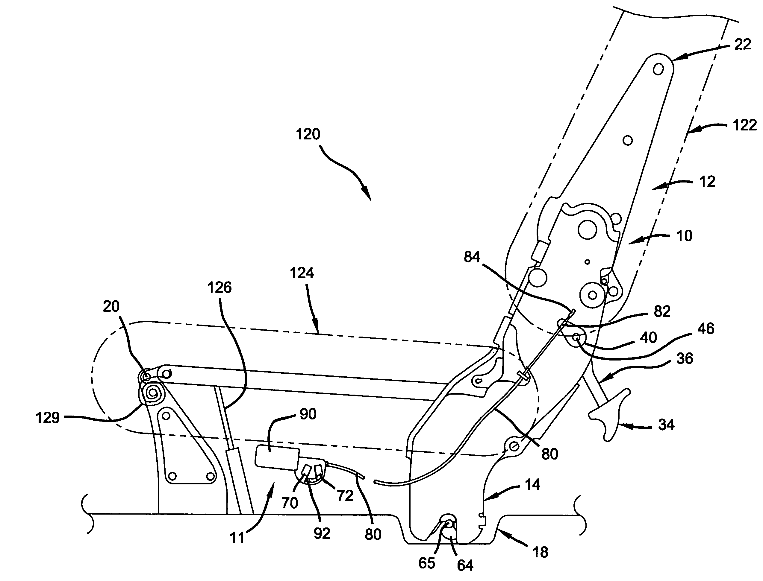
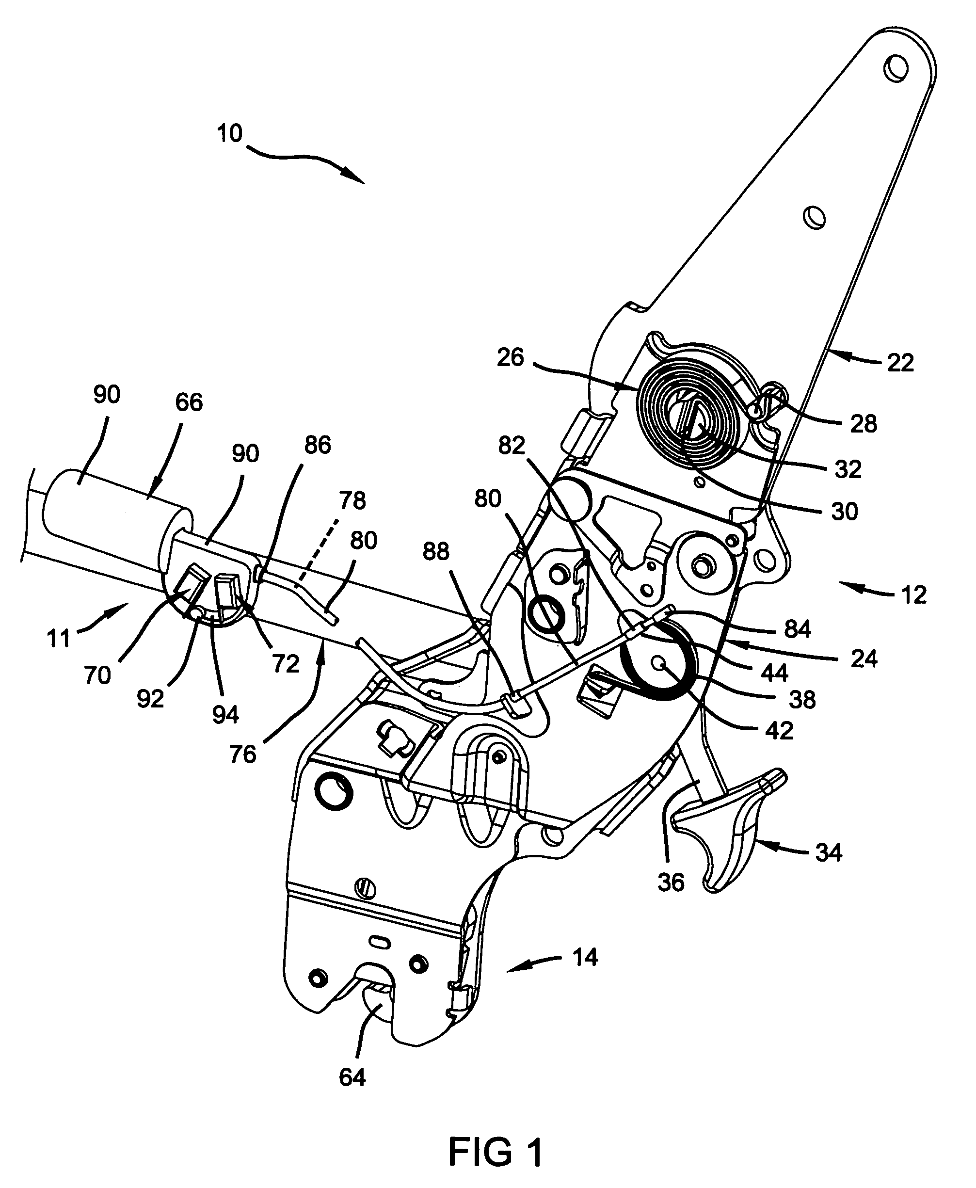
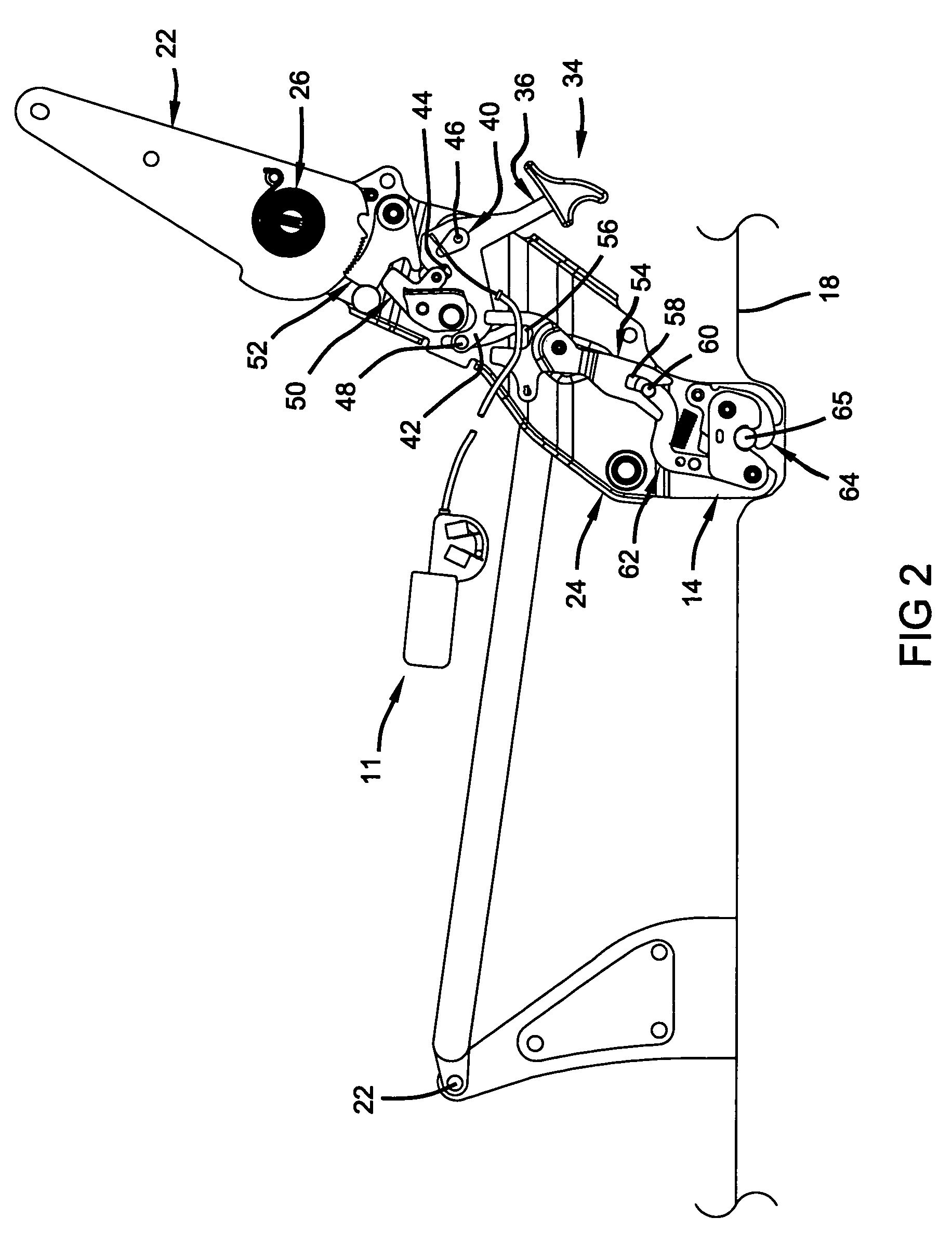
[0066]With particular reference to FIG. 9, the powered remote actuation device 11a is shown having a motor 66, an output 118, and a link 116.
[0067]In general, the powered remote actuation device 11a is substantially similar to the powered remote actuation device 11 described above. In view of the substantial similarity in structure and function of the components associated with the powered remote actuation device 11 and the powered remote actuation device 11a, like reference numerals are used here and in the drawings to identify like components.
[0068]The link 116 is rotatably attached to the motor output 118 at a first end and rotatably attached to the actuation handle 36 at a second end. In this manner, as the motor 66 drives the output 118, the link 116 is caused to translate, thereby imparting a rotational force (A) on the actuation handle 36, via lever 40, as shown in FIG. 9. As previously discussed, sufficient rotation of the actuation handle 36 will toggle the recliner and flo...
third embodiment
[0069]With particular reference to FIG. 10, the powered remote actuation device 11b is shown having a DC motor 66 driven by an external power source 67, a potentiometer 71, a controller 73, an actuation button 74, and a cable assembly 76.
[0070]In general, the powered remote actuation device 11b is substantially similar to the powered remote actuation device 11 described above. In view of the substantial similarity in structure and function of the components associated with the powered remote actuation device 11 and the powered remote actuation device 11b, like reference numerals are used here and in the drawings to identify like components.
[0071]The powered remote actuation device 11b applies a force to the lever 40 to thereby rotate the actuation handle 36, and toggle the recliner mechanism 12 and floor-latch mechanism 14 into the unlocked positions, as discussed previously. In doing so, the powered remote actuation device 11b obviates the need for a user to exert a force on the ac...
fourth embodiment
[0076]With particular reference to FIG. 11, the powered remote actuation device 11c is shown having a DC motor 66 driven by an external power source 67, a hall-effect sensor 75, a controller 73, an actuation button 74, and a cable assembly 76.
[0077]In general, the powered remote actuation device 11c is substantially similar to the powered remote actuation device 11b described above. In view of the substantial similarity in structure and function of the components associated with the powered remote actuation device 11b and the powered remote actuation device 11c, like reference numerals are used here and in the drawings to identify like components.
[0078]The hall-effect sensor 75 of the powered remote actuation device 11c is used in place of the potentiometer 71 of device 11b and serves to provide the controller 73 with positional information relating to the cable 78. The hall-effect sensor 75 may be mounted generally within the motor 66 and functions to count pulses, or rotations, of...
PUM
 Abstract
Description
Claims
Application Information
 - R&D
- Intellectual Property
- Life Sciences
- Materials
- Tech Scout
- Unparalleled Data Quality
- Higher Quality Content
- 60% Fewer Hallucinations
Browse by: Latest US Patents, China's latest patents, Technical Efficacy Thesaurus, Application Domain, Technology Topic, Popular Technical Reports.
© 2025 PatSnap. All rights reserved.Legal|Privacy policy|Modern Slavery Act Transparency Statement|Sitemap|About US| Contact US: help@patsnap.com


