Tamper barrier enclosure with corner protection

a technology of corner protection and tampering barrier, which is applied in the direction of casings/cabinets/drawers, electrical equipment casings/cabinets/drawers, packaging goods, etc., can solve the problems of overuse and waste of tamper wrap material, which is typically expensive, and is not viable, so as to prevent tampering

Inactive Publication Date: 2007-01-02
PITNEY BOWES INC
View PDF49 Cites 67 Cited by
  • Summary
  • Abstract
  • Description
  • Claims
  • Application Information

AI Technical Summary

Problems solved by technology

A significant problem with this method is that the corner edges 10 of the wrapped PCB 5 end up having a number of overlapping layers of the tamper wrap, referred to as mechanical stack up, due to the multiple folds that are required to wrap the PCB in its entirety.
These overlapping layers are cumbersome to deal with during assembly procedures and result in an overuse and waste of tamper wrap material, which is typically expensive.
Choosing not to cover such corner edges with the tamper wrap at all is not a viable solution to the problem of mechanical stack up since doing so would make the corner edges particularly vulnerable to attacks, such as through the introduction of a monitoring probe.

Method used


Image

  • Tamper barrier enclosure with corner protection
  • Tamper barrier enclosure with corner protection
  • Tamper barrier enclosure with corner protection

Examples


Embodiment Construction

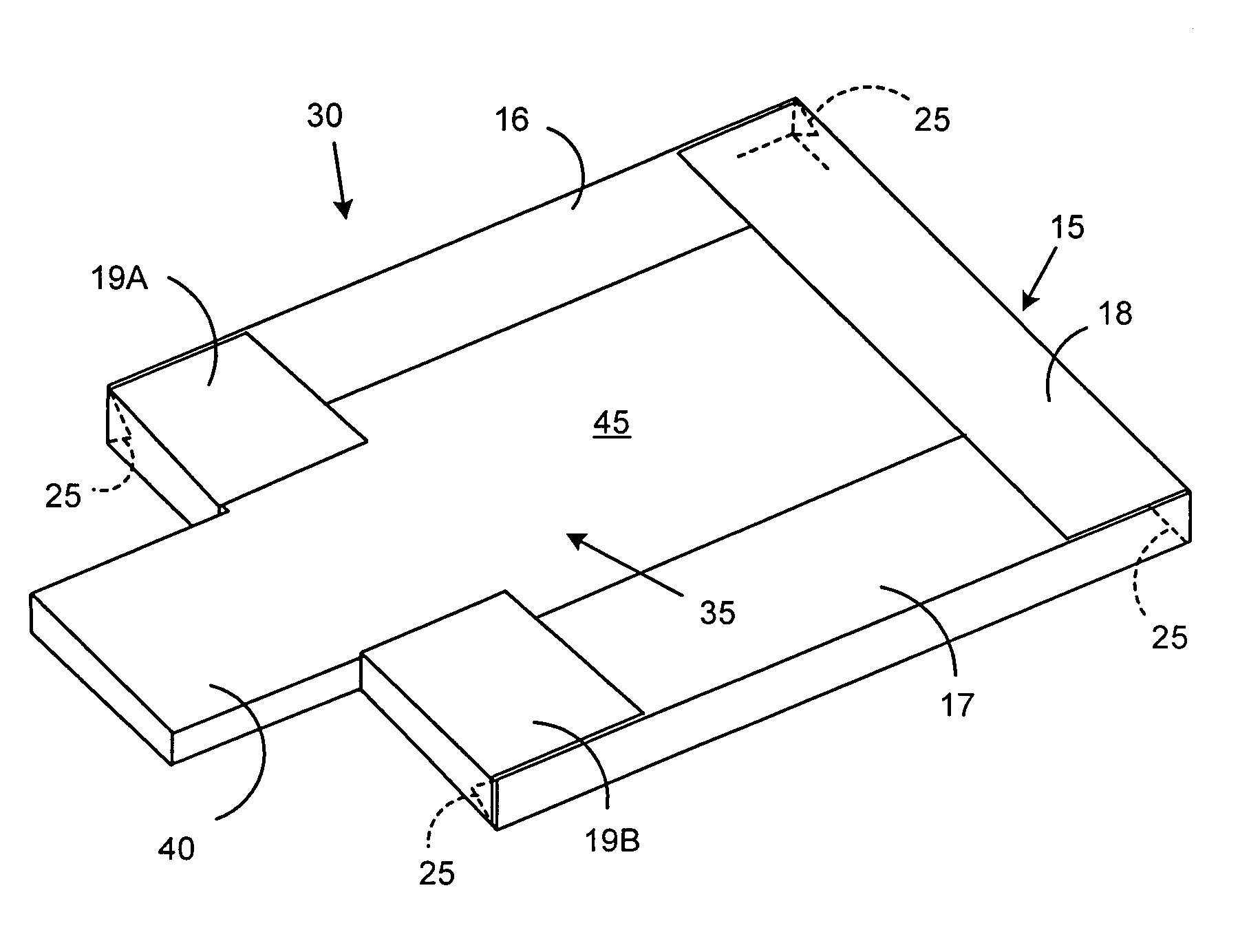
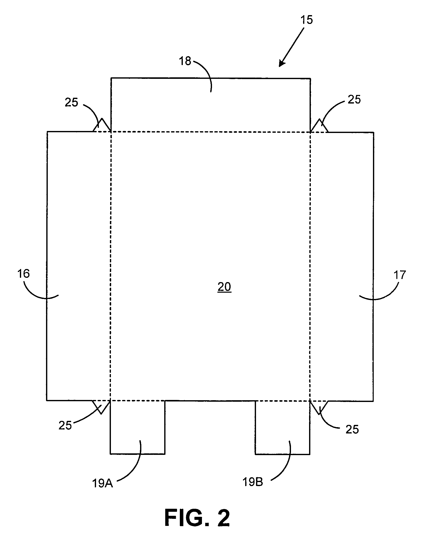
[0017]FIG. 2 is a top plan view of a first embodiment of tamper wrap 15 according to the present invention. Tamper wrap 15 is formed from a flexible film material. Tamper wrap 15 is intended to be wrapped around a PCB to protect the PCB from tampering attempts. In the preferred embodiment of the present invention, tamper wrap 15 includes first side tab 16 opposite second side tab 17 and third side tab 18 opposite fourth side tabs 19A and 19B, all extending from main body portion 20. Tamper wrap 15 also includes corner protection flaps 25 that extend from the ends of first side tab 16 and second side tab 17 at a point that is adjacent to the ends of third side tab 18 and fourth side tabs 19A and 19B. This preferred tamper wrap 15 shown in FIG. 2 is particularly adapted for use as part of the printed circuit board assembly described in the co-pending U.S. application Ser. No. 10 / 868,337, entitled “Tamper Barrier for Electronic Device” assigned to the assignee of the present invention,...


PUM


Abstract

A tamper protected printed circuit board assembly including a printed circuit board and a tamper wrap attached to the printed circuit board. The tamper wrap includes a plurality of side tabs extending from a main body portion and a plurality of corner protection flaps extending from the side tabs. The tamper wrap covers the entirety of a first surface of the printed circuit board and at least a portion of a second surface opposite the first surface of the printed circuit board. Each of the side tabs covers at least a portion of one of the side walls of the printed circuit board and each of the corner flaps is folded around and covers a respective one of the corner edges of the printed circuit board. The printed circuit board may have a plurality of corner sentinels mounted adjacent to the corners of a surface thereof for protecting such corners.

Description

FIELD OF THE INVENTION[0001]The present invention relates to tamper detection and protection for electronic circuitry, and more particularly, to a system for protecting a printed circuit board wrapped in a tamper barrier wrap from tamper attacks directed at the corners thereof.BACKGROUND OF THE INVENTION[0002]In many electronic applications, it is often desirable or even required to protect electronic circuitry, such as on a printed circuit board (PCB), from unlawful or unauthorized access. This is especially true for electronic circuitry that includes cryptographic modules or functionality. For example, postage security devices (PSDs) are required by the United States Postal Service to comply with FIPS 140-2 level 3 issued by the National Institute of Standards and Technology (NIST). FIPS 140-2 level 3 requires that PSDs have a full envelope of physical tamper protection and detection which encloses all electrical nodes.[0003]Prior art methods of tamper protection, such as disclose...

Claims


Application Information

Patent Timeline
Patent Type & Authority Patents(United States)
IPC IPC(8): B65D85/30A45C13/10H05K3/28H05K5/02
CPCH05K3/284H05K5/0208H05K1/0275Y10S206/807H05K2203/1311
Inventor CLARK, DOUGLAS AHEITMANN, KJELL APERREAULT, PAUL G
Owner PITNEY BOWES INC
Why Eureka
Try Eureka