
Occupant restraint system

a technology for occupants and restraints, applied in pedestrian/occupant safety arrangements, vehicular safety arrangments, vehicle components, etc., can solve the problems of reducing the distance between adjacent mounting portions and the inability to fix air bags, and achieve the effect of smooth deployment and smooth deploymen

Active Publication Date: 2007-01-09
HONDA MOTOR CO LTD
View PDF21 Cites 51 Cited by
  • Summary
  • Abstract
  • Description
  • Claims
  • Application Information

AI Technical Summary

Benefits of technology

[0007]According to the construction, since the belt-like protruding portions which extend longitudinally along the folded air bag are provided on the external portion of the air bag, the longitudinal dimension of the air bag is largely contracted when the air bag is twisted and hence, an interval between the adjacent mounting portions is decreased, thereby making it impossible for the air bag to be fixed. As a result, the air bag is assuredly prevented from being mounted in the twisted state, whereby the air bag is allowed to be deployed smoothly.
[0008]According to a second aspect of the invention, there is provided an occupant restraint system in which a folded air bag is fixed along a side portion of a roof, so that the air bag is inflated to be deployed in a curtain-like fashion along an inner side of a passenger compartment by gas generated from an inflator at the time of a collision of a vehicle, wherein a rod-like twist preventing member is fixed longitudinally along the folded air bag so that the twisting of the air bag is prevented by the twist preventing member so fixed.
[0009]According to the construction, since the rod-like twist preventing member is fixed longitudinally along the folded air bag, the air bag is disabled from being twisted. As a result, the air bag is assuredly prevented from being fixed in the twisted state, whereby the air bag is allowed to be deployed smoothly.

Problems solved by technology

According to the construction, since the belt-like protruding portions which extend longitudinally along the folded air bag are provided on the external portion of the air bag, the longitudinal dimension of the air bag is largely contracted when the air bag is twisted and hence, an interval between the adjacent mounting portions is decreased, thereby making it impossible for the air bag to be fixed.

Method used


Image

  • Occupant restraint system
  • Occupant restraint system
  • Occupant restraint system

Examples


first embodiment

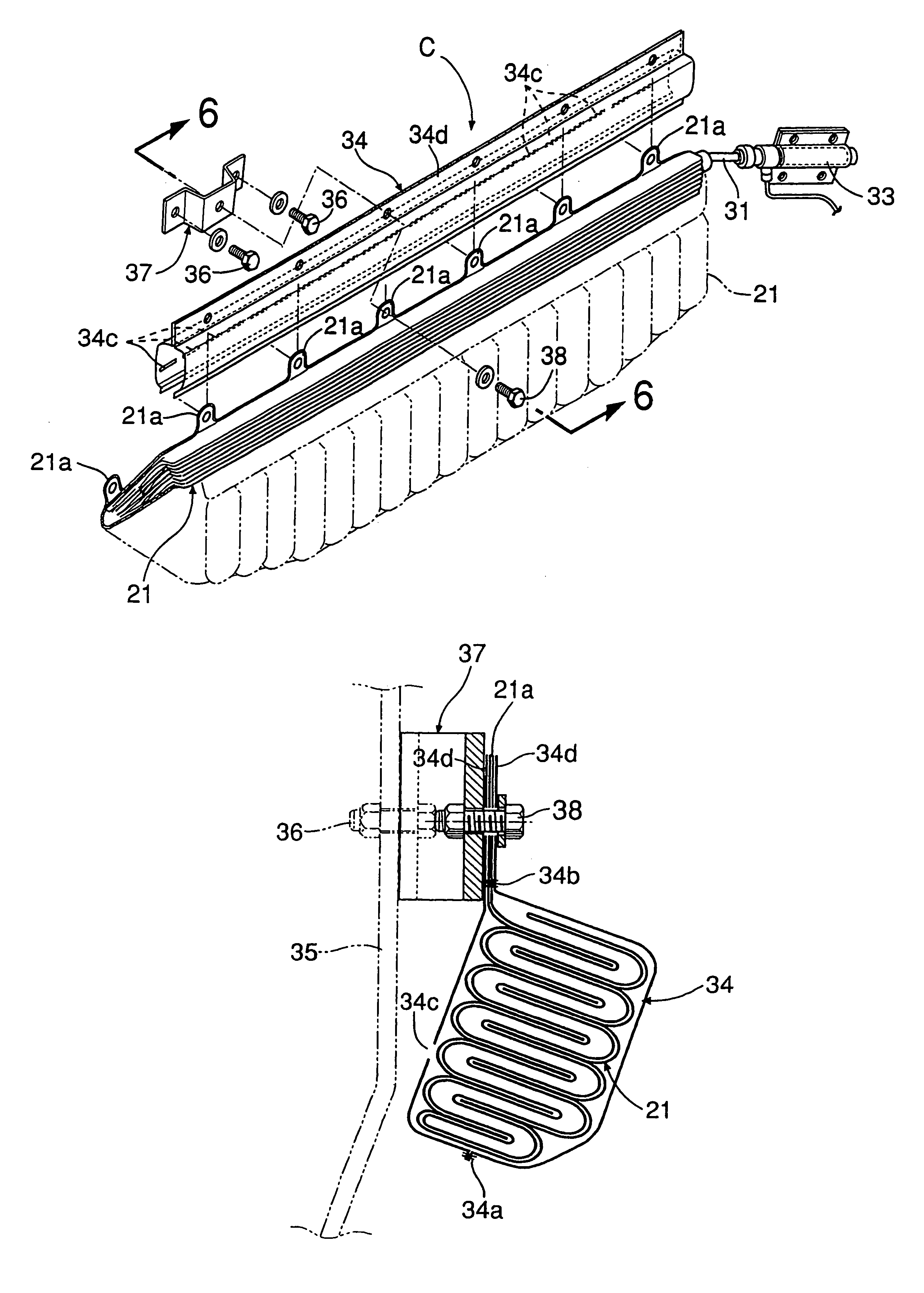
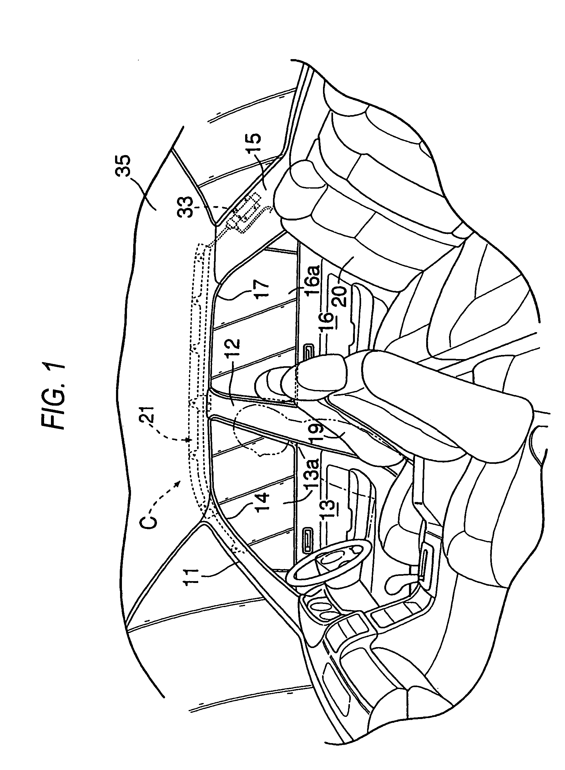
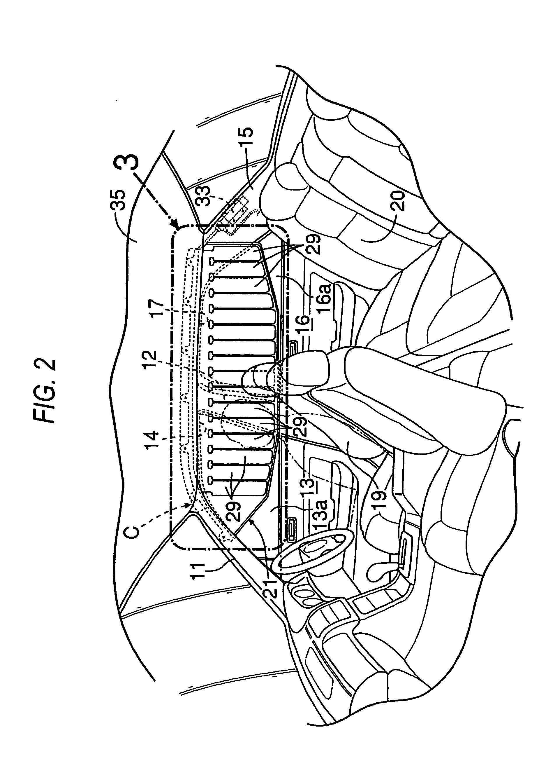
[0029]FIGS. 1 to 7 illustrate a first embodiment, in which FIG. 1 is a drawing showing the inside of a passenger compartment of an automobile when an air bag is not yet deployed, FIG. 2 is a drawing showing the inside of the passenger compartment of the automobile when the air bag is deployed, FIG. 3 is an enlarged view of a portion in FIG. 2 which is indicated by larger reference numeral 3, FIG. 4 is a cross-sectional view taken along the line 4—4 in FIG. 3, FIG. 5 is an exploded perspective view of an occupant restraint system, FIG. 6 is a cross-sectional view taken along the line 6—6 in FIG. 5, and FIG. 7 is a drawing explaining an operation of the air bag when twisted.

[0030]As shown in FIG. 1, in a side of a vehicle body of a vehicle, a door opening 14 is formed between front pillar 11 and a center pillar 12 for mounting therein a front side door 13 and a door opening 17 is mounted between the center pillar 12 and a rear pillar 15 for mounting therein a rear side door 16. A roof...

second embodiment

[0040]Next, the invention will be described based on FIGS. 8A and 8B.

[0041]While, in the first embodiment that is described above, the belt-like protruding portion 34d is provided on the air bag cover 34 which covers the folded air bag 21, in a second embodiment, a belt-like protruding portion 21b is formed integrally along an upper edge of an air bag 21. This belt-like protruding portion 21b also functions as the plurality of mounting portions 21a provided on the air bag 21 described in the first embodiment.

[0042]Thus, a similar function and advantage to those attained by the first embodiment can also be attained by the second embodiment.

third embodiment

[0043]Next, the invention will be described based on FIGS. 9A and 9B.

[0044]A third embodiment is such as to add a protector 39 to the second embodiment that is described above. The protector 39 is formed of an extremely thin synthetic resin in such a manner as to facilitate the deflection thereof and includes a main body portion 39a which extends longitudinally in a belt-like fashion along the folded air bag 21, a belt-like protruding portion 39b which extends along an upper edge of the main body portion 39a, and a plurality of protecting portions 39c which extend from a lower edge of the main body portion 39a at positions corresponding to the front pillar 11, the center pillar 12 or the rear pillar 15 in such a manner as to hold a bottom side of the air bag 21. When the belt-like protruding portion 21b on the air bag 21 is fixed to the brackets 37 with the bolts 38, the belt-like protruding portion 39b on the protector 39 is superimposed on the belt-like protruding portion 21b on t...


PUM


Abstract

A belt-like protruding portion 34d extending longitudinally is provided on an air bag cover 34 which covers a folded air bag 21. In the event that the air bag 21 is twisted when the air bag 21 is mounted on a vehicle body, a longitudinal dimension of the air bag 21 is contracted largely, whereby an interval between adjacent mounting portions 21a is decreased, thereby the fixing of the air bag 21 being disabled. As a result, the fixing of the air bag 21 in the twisted state is prevented assuredly, and the smooth deployment of the air bag 21 is enabled. A rod-like twist preventing member may be fixed longitudinally along the folded air bag 21 instead of the belt-like protruding portion 34d.

Description

BACKGROUND OF THE INVENTION[0001]The present invention relates to an occupant restraint system for deploying a folded air bag in a curtain-like fashion from a side portion of a roof along an inner side of a passenger compartment of a vehicle.[0002]Since the air bag of the occupant restraint system is formed into an elongated string-like shape when folded, there exists a possibility that the air bag so folded is twisted when mounted on a vehicle body, and in the event that the air bag is mounted on the vehicle body in a twisted state, a smooth deployment is disrupted. To solve that problem, a mark was imparted on the surface of a folded air bag so that the folded air bag is mounted on the vehicle body in an untwisted state by visually watching the mark, which is known by the following patent literature.[0003]Japanese Examined Patent Publication No. 3113977[0004]However, since the conventional occupant restraint system was such as to prevent the twisting of the folded air bag by an as...

Claims


Application Information

Patent Timeline
IPC IPC(8): B60R21/16B60R21/20B60R21/213B60R21/215B60R21/201B60R21/237
CPCB60R21/201B60R21/213B60R21/237B60R21/232
Inventor OCHIAI, FUMIHARUKAWAJIRI, NAOKIFUKUDA, TAKERU
Owner HONDA MOTOR CO LTD
Features
  • Generate Ideas
  • Intellectual Property
  • Life Sciences
  • Materials
  • Tech Scout
  • Unparalleled Data Quality
  • Higher Quality Content
  • 60% Fewer Hallucinations
Learn More