
Thin-film tape head having single groove formed in head body and corresponding process

Inactive Publication Date: 2007-01-09
IBM CORP
View PDF9 Cites 5 Cited by
  • Summary
  • Abstract
  • Description
  • Claims
  • Application Information

AI Technical Summary

Benefits of technology

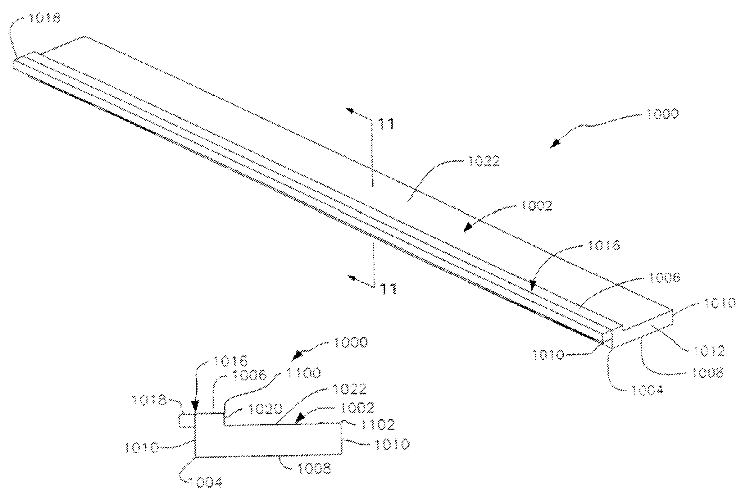
[0015]A magnetic head according to one embodiment includes a head body with a substantially rectangular configuration including a top face, a bottom face, a pair of elongated side faces, and a pair of short end faces; at least one transducer formed in communication with the top face of the head body; a closure with a substantially rectangular configuration having a length substantially equal to the head body, the closure coupled to a first one of the side faces of the head body coincident with the top face thereof; and a single groove formed in the top face of the head body and extending bet

Problems solved by technology

Absent such alignment, the operation of the head 300 may be compromised.
Yet another problem arises when attempting to dice the heads 300 on a wafer.
Recently, however, the use of the closures 302 such as that shown in FIG. 3 has complicated such process.
This bending, in turn, results in non-planarity in the operating surface 406 of the head 402.
As is well known, each action that is required during the process of thin-film magnetic head manufacture creates much expense.

Method used


Image

  • Thin-film tape head having single groove formed in head body and corresponding process
  • Thin-film tape head having single groove formed in head body and corresponding process
  • Thin-film tape head having single groove formed in head body and corresponding process

Examples


Embodiment Construction

[0033]The following description is the best embodiment presently contemplated for carrying out the present invention. This description is made for the purpose of illustrating the general principles of the present invention and is not meant to limit the inventive concepts claimed herein.

[0034]Beam and Magnetic Head Bonding Apparatus

[0035]FIG. 6 is a perspective view of an apparatus 600 for precisely attaching a thin-film head to a beam. As will soon become apparent, this is accomplished by allowing relative alignment of the head and the beam in six directions 601. Such directions 601 are shown in the lower right-hand corner of FIG. 6. For further detail regarding the components of the present apparatus 600 of FIG. 6, FIG. 6A illustrates an exploded view showing the various components along with the associated fasteners, couplings, etc. of the apparatus 600.

[0036]In the context of the present embodiment, a head may refer to any magnetic head capable of operating (i.e. reading, writing...


PUM

PropertyMeasurementUnit
Lengthaaaaaaaaaa
Angleaaaaaaaaaa

Abstract

A magnetic head according to another embodiment includes a head body including a top face, a bottom face, a pair of elongated side faces, and a pair of short end faces; at least one transducer formed in communication with the top face of the head body; and a single groove formed in the top face of the head body and extending between the transducers and one of the side faces of the head body. A method for manufacturing a magnetic head is also presented.

Description

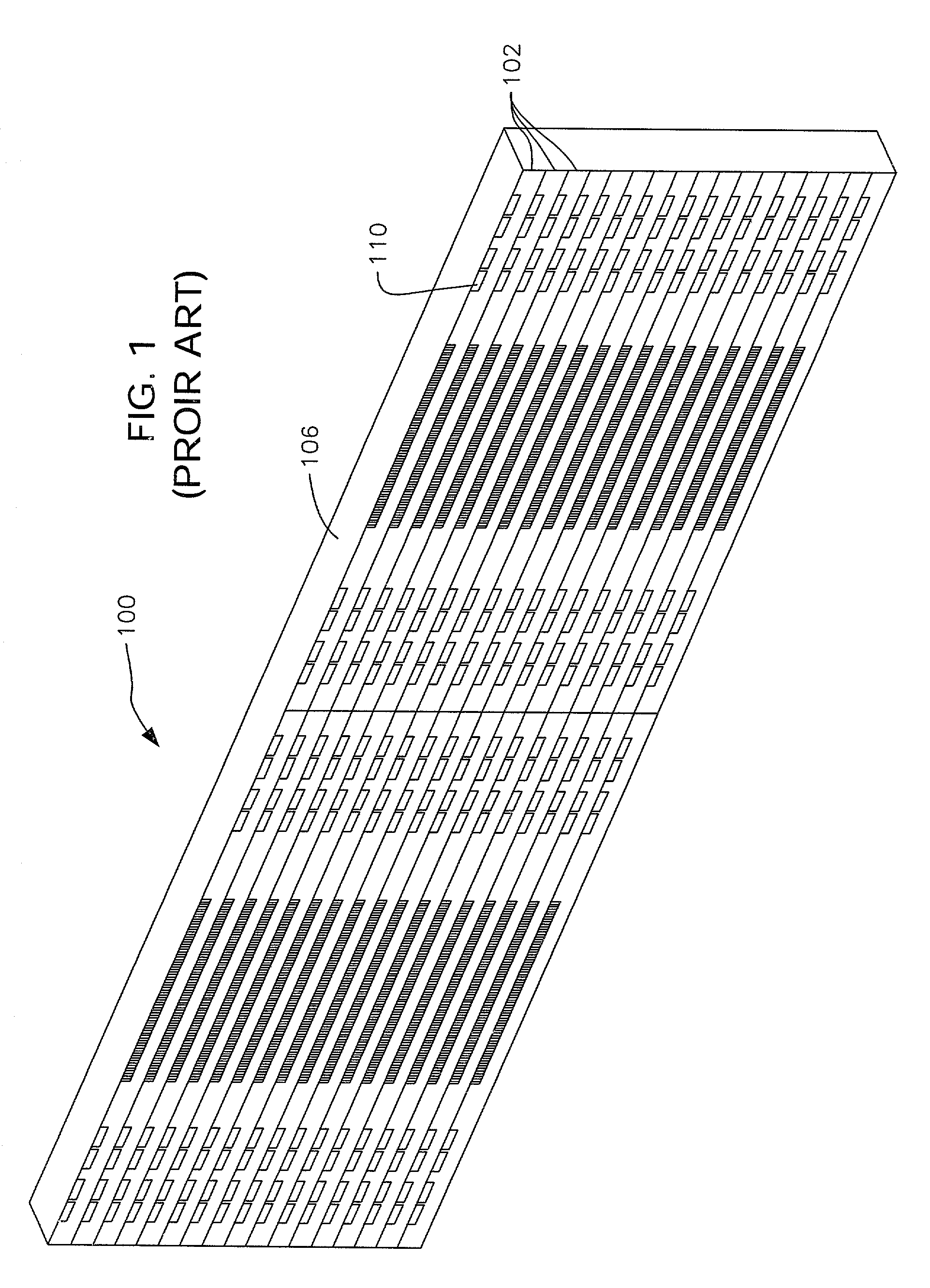
FIELD OF THE INVENTION[0001]The present invention relates to thin-film recording heads, and more particularly, this invention relates to improving the manufacturing process of thin-film recording heads and the structure thereof.BACKGROUND OF THE INVENTION[0002]Conventional recording heads for linear tape drives have small transducers incorporated into a large head assembly to span the full width of the tape. For recording heads fabricated using thin-film wafer technology, this requires that the head either be fabricated individually on a wafer which is at least as wide as the recording tape and lapped individually to the proper shape, or be fabricated as a small part and assembled with larger pieces and the full assembly lapped individually to the proper shape.[0003]Prior art FIG. 1 illustrates a wafer 100 on which a plurality of heads 102 may be manufactured. As shown, the wafer 100 includes two columns of multiple rows of heads 102. During the fabrication of the wafer 100, an arra...

Claims


Application Information

Patent Timeline
IPC IPC(8): G11B5/187G11B5/60G11B5/31G11B5/584G11B5/588
CPCG11B5/3103G11B5/3173G11B5/588G11B5/584G11B5/1871G11B5/3116G11B5/3163Y10T29/53165Y10T29/49021Y10T29/49044Y10T29/49032
Inventor BISKEBORN, ROBERT G.DESHPANDE, ANNAYYA P.LO, CALVIN S.LUONG, KEVIN T.TAINA, ABEL J.TORRES, ARTEMIO-JUAN
Owner IBM CORP
Features
  • Generate Ideas
  • Intellectual Property
  • Life Sciences
  • Materials
  • Tech Scout
  • Unparalleled Data Quality
  • Higher Quality Content
  • 60% Fewer Hallucinations
Learn More