Image forming apparatus that controls image forming process based on temperature of conveying belt

a technology of conveying belt and temperature control, which is applied in the direction of electrographic process apparatus, optics, instruments, etc., can solve the problems of deteriorating flowability of toner in each image forming unit, reducing the number of continuous print copies, and reducing the quality of image forming units, so as to reduce internal temperature and improve image quality.

Active Publication Date: 2007-01-23
OKI ELECTRIC IND CO LTD
View PDF16 Cites 13 Cited by
  • Summary
  • Abstract
  • Description
  • Claims
  • Application Information

AI Technical Summary

Benefits of technology

[0009]It is an object of the invention to solve the problems of the conventional image forming apparatus mentioned above

Problems solved by technology

However, in the above conventional image forming apparatus, when a temperature in the image forming apparatus rises because of an environmental change or an increase in the number of print copies which are continuously printed, that is, the number of con

Method used


Image

  • Image forming apparatus that controls image forming process based on temperature of conveying belt
  • Image forming apparatus that controls image forming process based on temperature of conveying belt
  • Image forming apparatus that controls image forming process based on temperature of conveying belt

Examples


second embodiment

[0156]The second embodiment will now be described.

[0157]FIG. 10 is a flowchart showing the operation of a printer in the second embodiment of the invention. FIG. 11 is a waveform diagram showing the operation of the printer in the second embodiment of the invention. In FIG. 11, an axis of abscissa indicates the number of print copies and an axis of ordinate shows the detection temperature Tb.

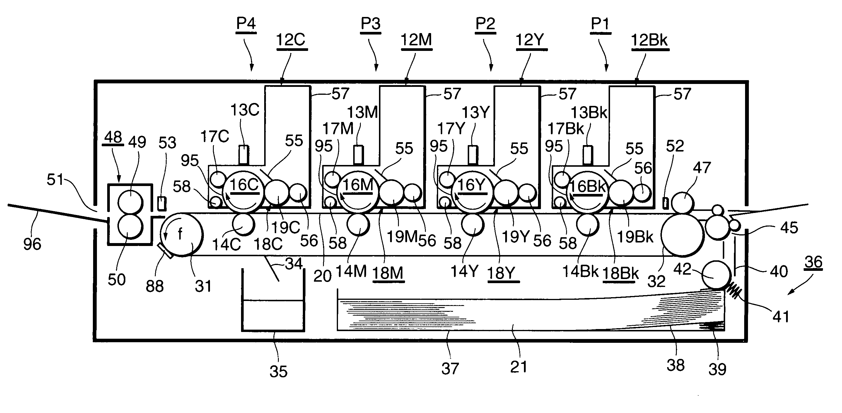
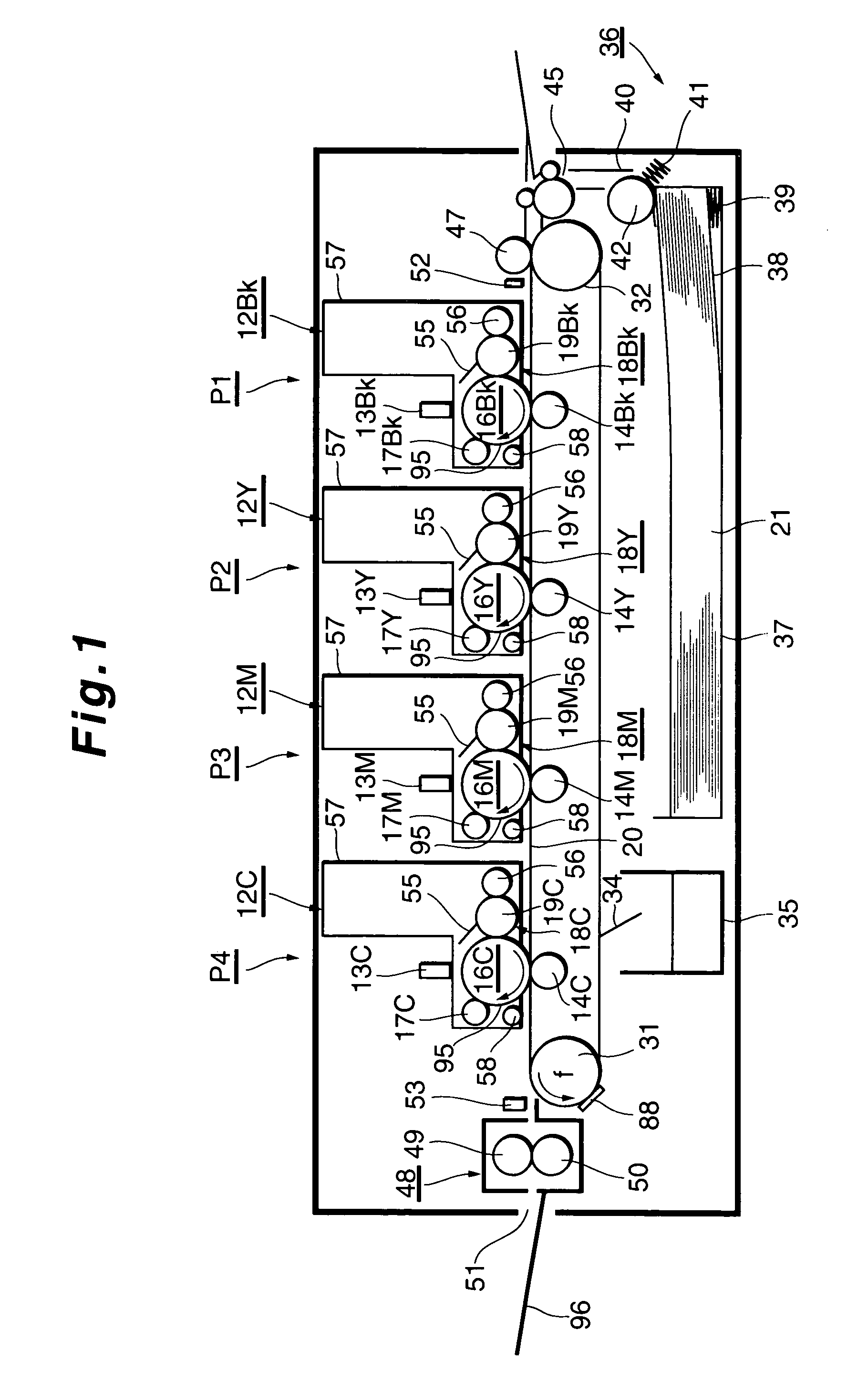
[0158]In the printer, as shown in FIG. 1, since the photosensitive drums 16Bk (FIG. 1), 16Y, 16M, and 16C as image holding materials and the temperature detecting sensor 88 as a temperature detecting unit are arranged so as to be away from each other, the surface temperatures of the photosensitive drums 16Bk, 16Y, 16M, and 16C and the detection temperature Tb do not perfectly coincide. Actually, the detection temperature Tb is higher than the temperatures of the photosensitive drums 16Bk, 16Y, 16M, and 16C by a few degrees (Δt [° C.]) due to the structure of the printer, the setting position of ...

first embodiment

[0163]In this case, since it is sufficient to add the offset value for correction to the threshold value φ1, a temperature table similar to that in the first embodiment can be used. Therefore, the costs of the image forming apparatus can be reduced.

[0164]Since the threshold value is changed in dependence on the structure of the printer, the setting position of the cooling means, the structure of the exhaust duct, and the like, the standby mode setting process can be executed at a temperature near the temperatures of the photosensitive drums 16Bk, 16Y, 16M, and 16C as close as possible. Consequently, the image quality can be further improved.

[0165]Although the threshold value φ2 is corrected by adding the predetermined offset value for correction thereto in the embodiment, the detection temperature Tb can be corrected by subtracting the offset value for correction from the detection temperature Tb.

[0166]The flowchart of FIG. 10 will now be described.[0167]Step S11: Whether the detect...

third embodiment

[0173]the invention in which the different offset value for correction is set every temperature will now be described.

[0174]FIG. 12 is a flowchart showing the operation of a printer in the third embodiment of the invention. FIG. 13 is a waveform diagram showing the operation of the printer in the third embodiment of the invention. In FIG. 13, an axis of abscissa indicates the number of print copies and an axis of ordinate shows the detection temperature Tb.

[0175]In an elevating area before the surface temperatures of the photosensitive drums 16Bk (FIG. 1), 16Y, 16M, and 16C as image holding materials and the detection temperature Tb are saturated, if the uniform offset value for correction is set, there is a case where the surface temperatures of the photosensitive drums 16Bk, 16Y, 16M, and 16C and the detection temperature Tb do not coincide. That is, when the printing is started and the control of the fixing device 48 as a fixing unit is started, since the arranging positions of t...


PUM


Abstract

An image forming apparatus such as a printer has: an image forming unit which forms an electrostatic latent image onto a charged photosensitive drum, deposits toner onto the image, and forms a visible image; a belt arranged so as to run freely in contact with the image forming unit; a temperature sensor which detects a temperature of the belt; and a controller which controls an image forming process on the basis of the detected temperature. Since the belt temperature is detected and the printing process is controlled on the basis of the detected temperature, an increase in temperature of the drum and an increase in temperature in the printer can be suppressed. Thus, the flowability of the toner in each image forming unit does not deteriorates and image quality can be improved.

Description

BACKGROUND OF THE INVENTION[0001]1. Field of the Invention[0002]The invention relates to an image forming apparatus.[0003]2. Related Background Art[0004]Hitherto, in an image forming apparatus, for example, a color printer, a copying apparatus, a facsimile apparatus, or the like, printing mechanisms of colors of black, yellow, magenta, and cyan are provided. Each printing mechanism constructs an ID (Image Drum) unit and has: an image forming unit for forming a toner image of the relevant color; a copy transfer member for sequentially laying the toner image of the color formed by the image forming unit and transferring onto a recording medium; and the like. In each image forming unit, a toner cartridge is detachably arranged into a main body of the image forming unit and toner of the color is supplied to the image forming unit from a supply port formed in a lower portion of each toner cartridge.[0005]The recording media are picked up and fed one by one from a sheet enclosing cassette...

Claims


Application Information

Patent Timeline
IPC IPC(8): G03G15/00G03G21/20
CPCG03G15/50G03G15/5054G03G2215/0119G03G2215/00084
Inventor INOUE, HIROYUKIISHIKURO, TAKEMASAASABA, TAKESHI
Owner OKI ELECTRIC IND CO LTD
Why Eureka
Try Eureka