Image reading and recording apparatus having a cartridge dismounting space between a fixing unit and an exposing unit

a technology of image reading and recording apparatus, which is applied in the direction of electrographic process apparatus, instruments, optics, etc., can solve the problems of poor fixation heat is liable to fill the interior of the apparatus, and internal temperature of the apparatus is liable to rise, so as to suppress the rise of internal temperature and improve the mounting and dismounting operability of process cartridges.

Inactive Publication Date: 2010-04-06
CANON KK
View PDF16 Cites 0 Cited by
  • Summary
  • Abstract
  • Description
  • Claims
  • Application Information

AI Technical Summary

Benefits of technology

[0009]The present invention has been made in view of the above-noted points and the object thereof is to provide an image reading and recording apparatus which is improved in the mounting and dismounting operability of a process cartridge, and further suppresses the rise of the internal temperature of the apparatus caused by the heat from the fixing device.

Problems solved by technology

Also, the fixing device 53 is located in the lower portion of the apparatus, and this has led to the problem that the fixing heat thereof is liable to fill the interior of the apparatus and the internal temperature of the apparatus is liable to rise.
This has led to the problem that the mounting and dismounting operability of the process cartridge is poor.

Method used


Image

  • Image reading and recording apparatus having a cartridge dismounting space between a fixing unit and an exposing unit
  • Image reading and recording apparatus having a cartridge dismounting space between a fixing unit and an exposing unit
  • Image reading and recording apparatus having a cartridge dismounting space between a fixing unit and an exposing unit

Examples


Embodiment Construction

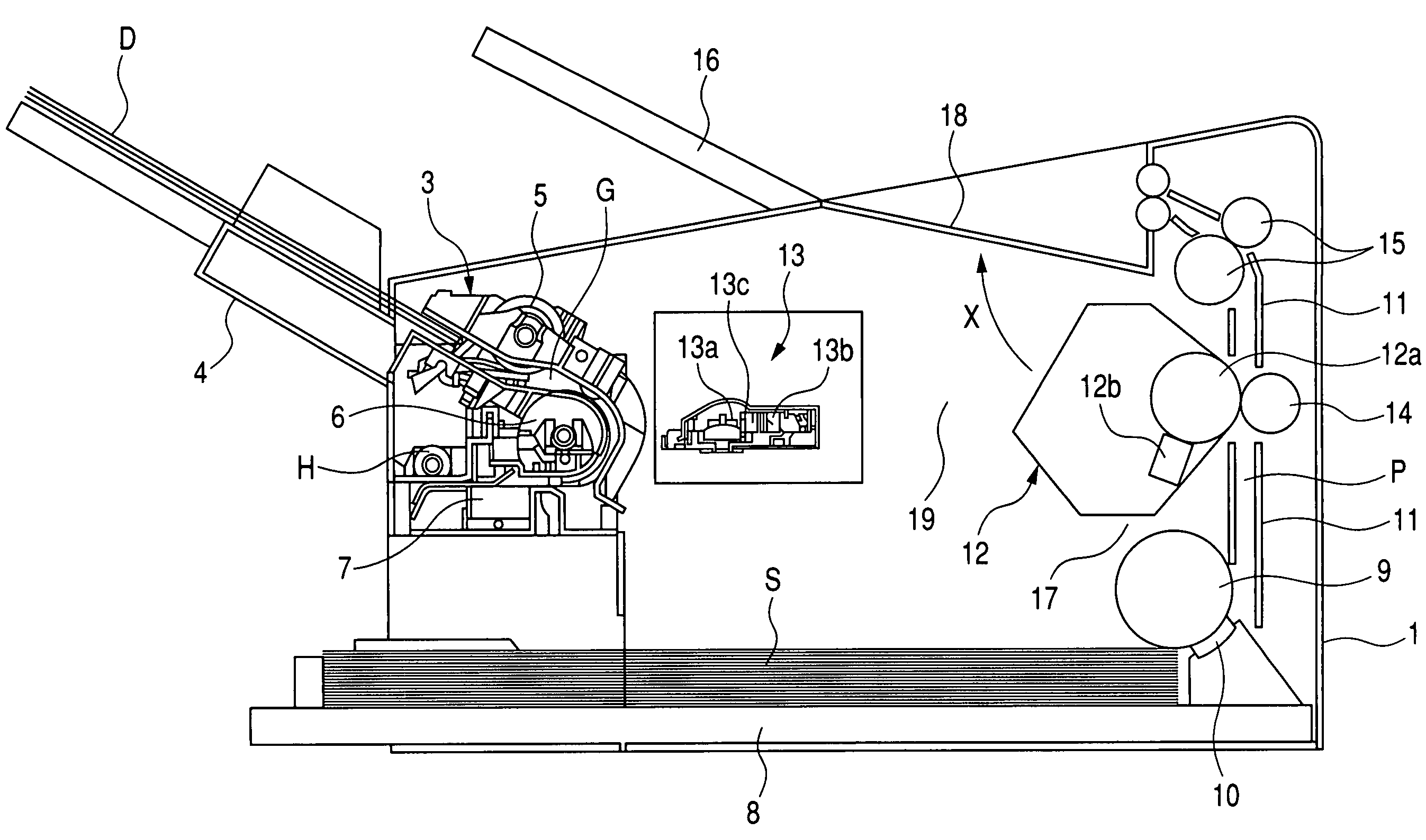
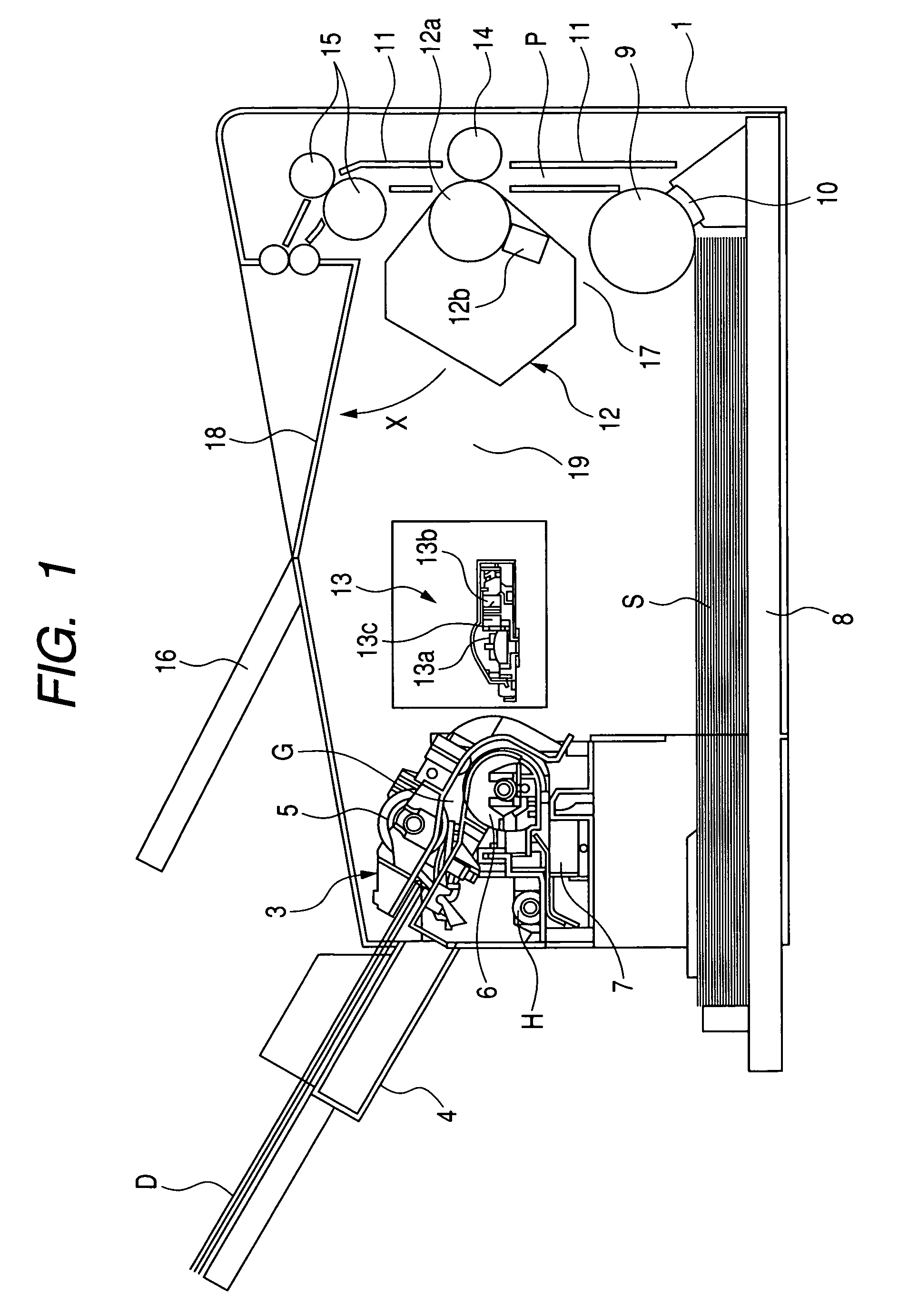
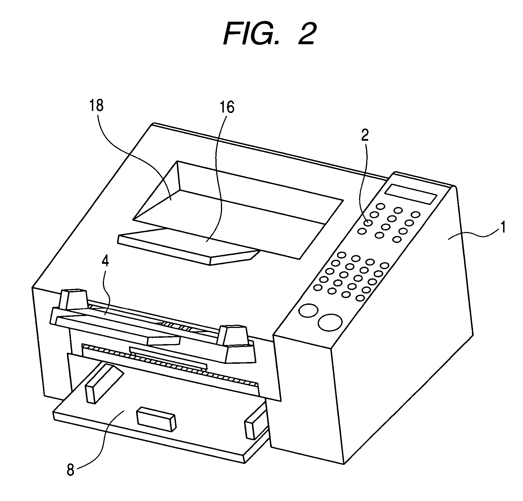
[0015]An image reading and recording apparatus according to an embodiment of the present invention will hereinafter be described with reference to the drawings. FIG. 1 is a typical cross-sectional illustration of the image reading and recording apparatus, FIG. 2 is a perspective view of the image reading and recording apparatus, and FIG. 3 is a schematic illustration of the detachably mounted state of a process cartridge.

{General Construction of the Image Reading and Recording Apparatus}

[0016]The general construction of the image reading and recording apparatus will first be described. In the present embodiment, a facsimile apparatus provided with copying and printer functions is shown as an example of the image reading and recording apparatus.

[0017]The image reading and recording apparatus according to the present embodiment has an operating panel 2 (see FIG. 2) for performing various operations provided on the upper surface of an apparatus main body. An operator operates the opera...


PUM


Abstract

An image reading and recording apparatus has a scanner unit for effecting exposure conforming to an image signal on a photosensitive drum, a heat roller pair for fixing a toner image formed on a recording sheet, and a reading unit for reading an original. The heat roller pair is disposed above a process cartridge, and a cartridge dismounting space for permitting dismounting of the process cartridge therethrough is disposed between the heat roller pair and the scanner unit.

Description

BACKGROUND OF THE INVENTION[0001]1. Field of the Invention[0002]This invention relates to an image reading and recording apparatus such as a copying machine, a facsimile apparatus or a multi-function printer.[0003]2. Related Background Art[0004]Nowadays, in copying machines, facsimile apparatuses, etc., recording of a high quality is possible and therefore, apparatuses of an electrophotographic type have come widely into use, and have also come to be used in personal use.[0005]As shown, for example, in FIG. 4 of the accompanying drawings, there is an apparatus for forming an image on a recording medium by an image forming portion 50 having a photosensitive drum and a developing device (see Japanese Utility Model Application Laid-Open No. H05-5464). In case of image forming, a recording medium is conveyed along a conveying path 51 formed in the lower portion of the apparatus. At the same time, a laser beam is applied from a scanner, not shown, to the photosensitive drum of the image ...

Claims


Application Information

Patent Timeline
Patent Type & Authority Patents(United States)
IPC IPC(8): G03G21/20G03G21/16G03G21/18H04N1/00
CPCH04N1/00519H04N1/00978H04N1/00543H04N2201/0091G03G15/00G03G21/20
Inventor KATAYAMA, TAKAFUMINAKAMURA, FUMIHIKOYAMAMOTO, TATSUYUKI
Owner CANON KK
Why Eureka
Try Eureka