Toolbox

a toolbox and tool technology, applied in the field of tools, can solve the problems of user injury, tool holding to the holders, and the falling of the rack b>120/b>, and achieve the effect of preventing the user from falling o

Inactive Publication Date: 2007-01-30
CHEN TSAI CHING
View PDF4 Cites 49 Cited by
  • Summary
  • Abstract
  • Description
  • Claims
  • Application Information

AI Technical Summary

Benefits of technology

[0007]The primary advantage of the toolbox according to the present invention is the including of elastic elements for retaining the lateral and central holders in the stick-out position. Another advantage is that the lateral and central holders are not hindered by one another.

Problems solved by technology

However, the weight of the tools held by the holders 160 often causes the rack 120 to fall.
Such accidental closing causes a user troubles in getting the tools.
Moreover, while taking tools from the case 130, a user would get hurt by the tools held to the holders 160.

Method used


Image

  • Toolbox
  • Toolbox
  • Toolbox

Examples


Embodiment Construction

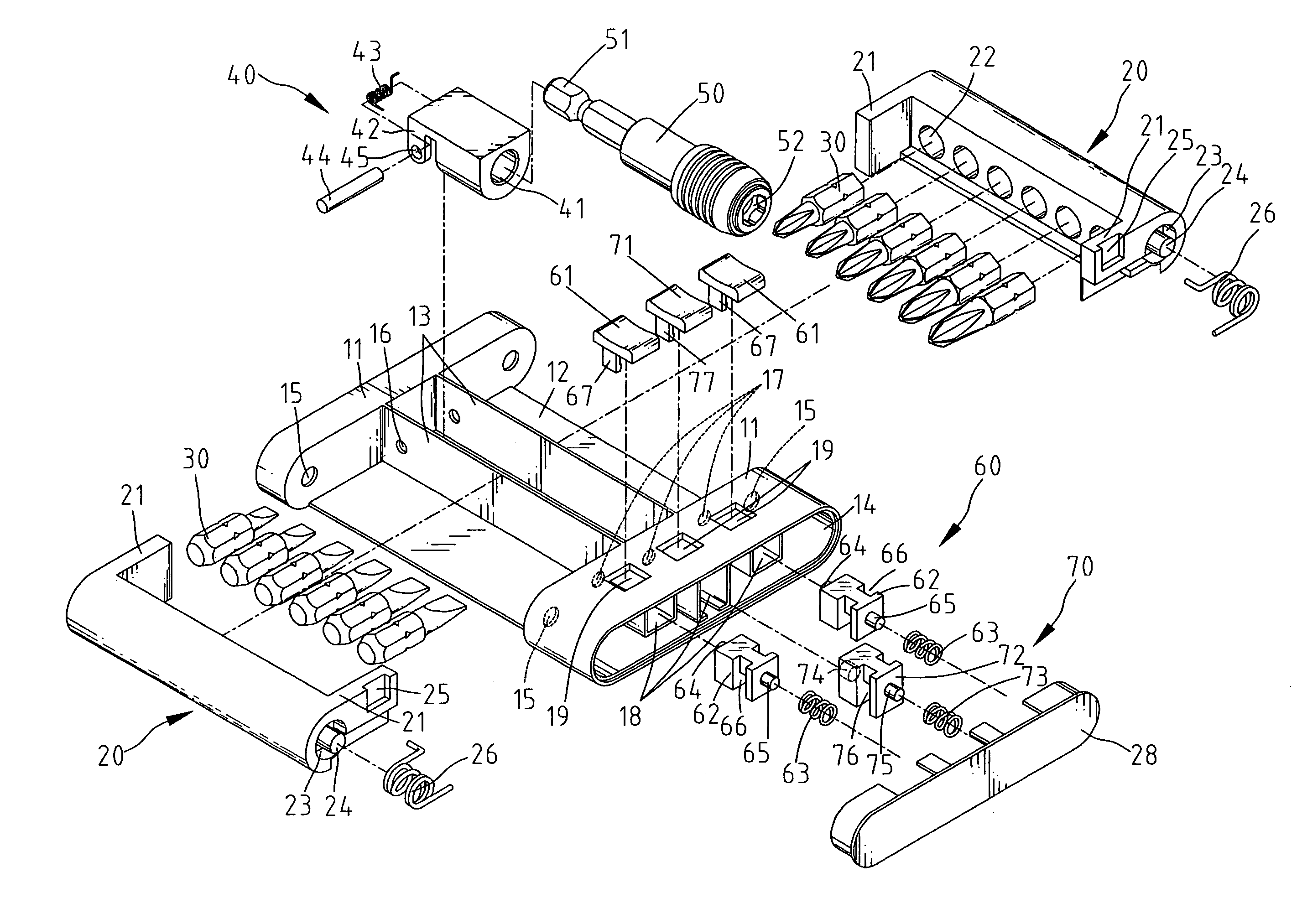
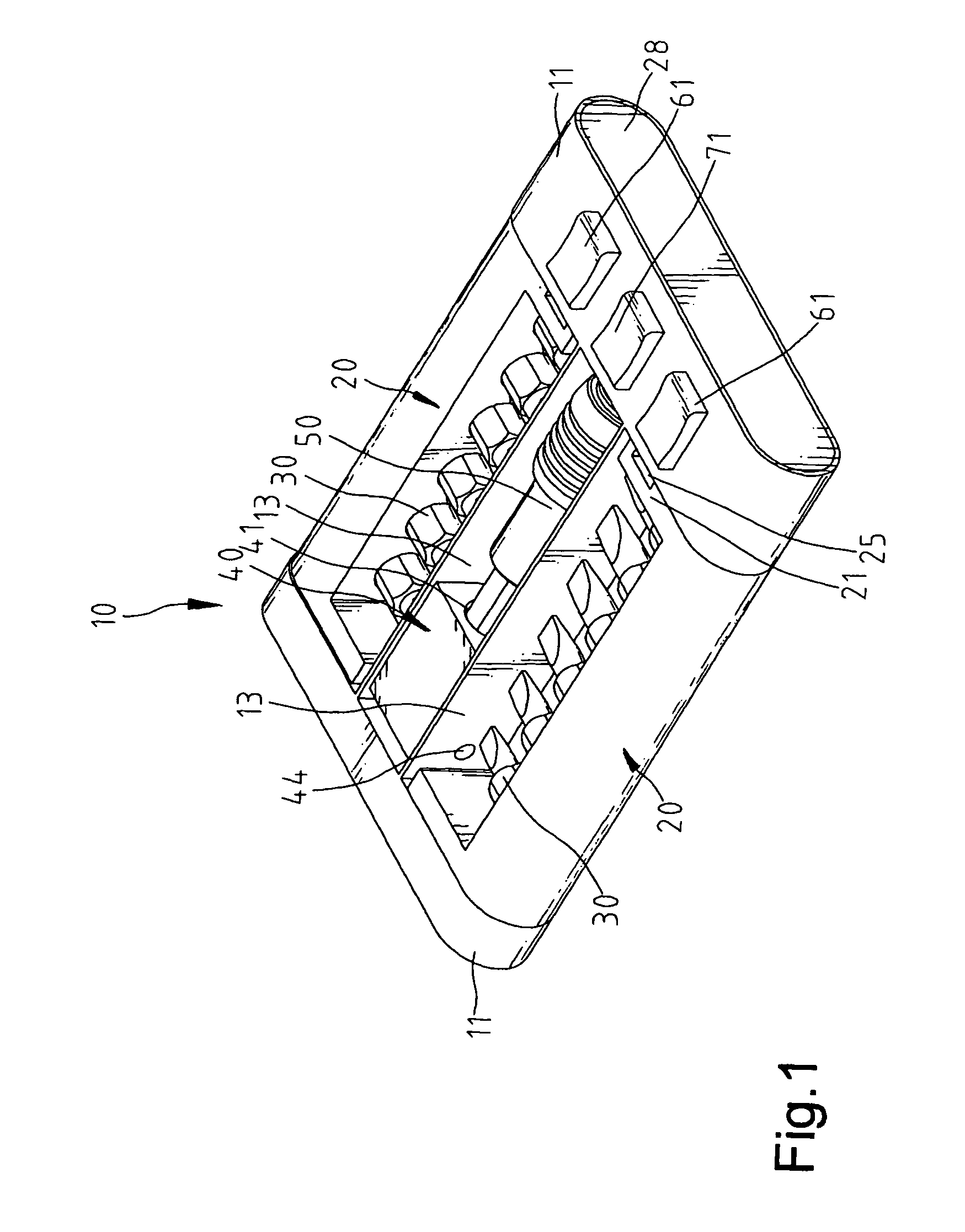
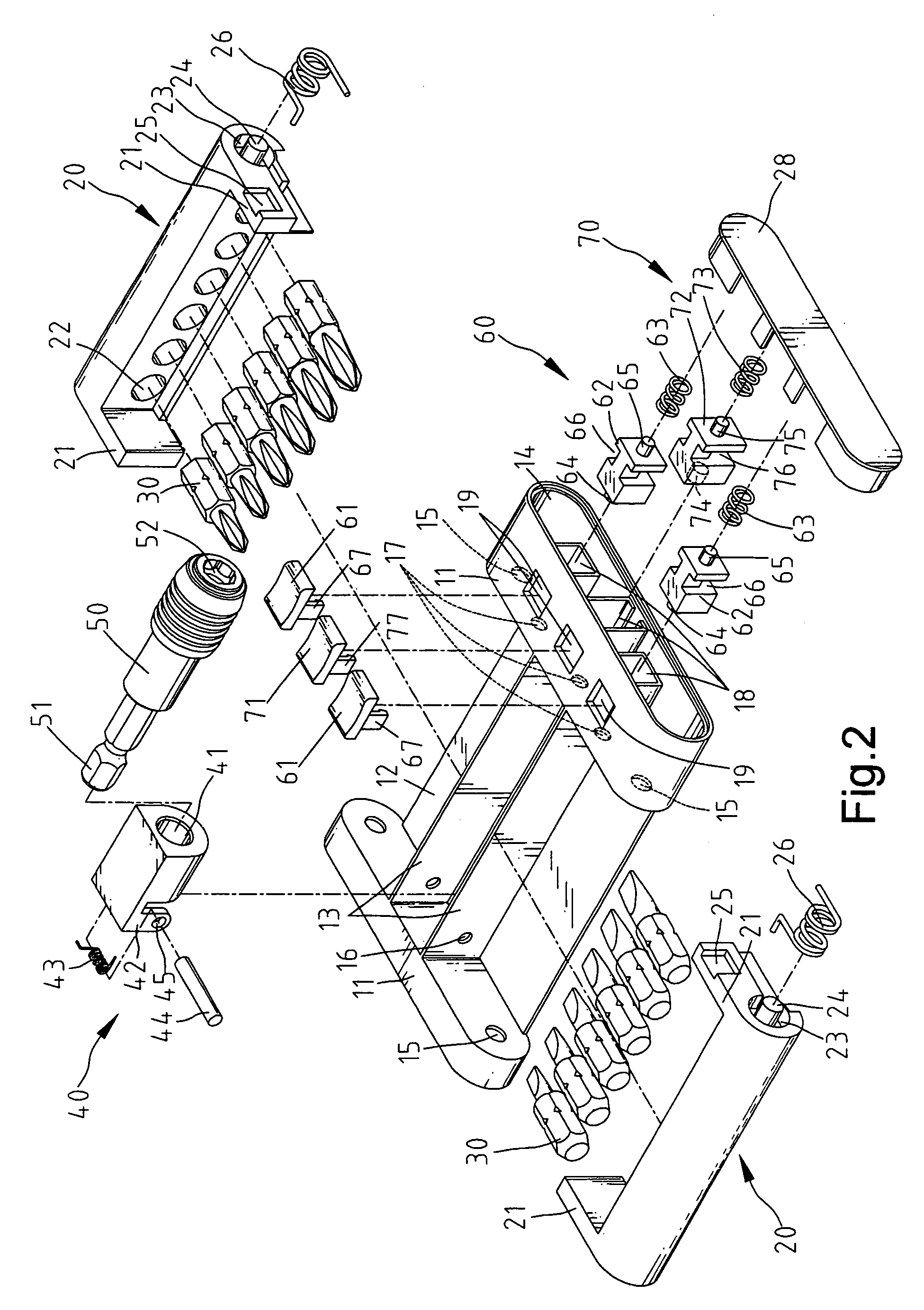
[0021]Referring to FIGS. 1 and 2, according to the preferred embodiment of the present invention, a toolbox includes a body 10, two lateral holders 20 pivotally connected with the body 10 between a lie-down position and a stick-out position, a central holder 40 pivotally connected with the body 10 between a lie-down position and a stick-out position, two lateral locks 60 for locking the lateral holders 20 in the lie-down position and a central lock 70 for locking the central holder 40 in the lie-down position.

[0022]The body 10 includes a board 12, front and rear walls 11 on the board 12, two partitions 13 on the board 12, and a frame 14 extending forwards from the front wall 11. Each wall 11 defines two apertures 15. The front wall 11 defines three holes 17. Three sub-frames 18 are formed on a lower side of an upper member of the frame 14. Three windows 19 are defined in the upper member of the frame 14.

[0023]Each lateral holder 20 includes front and rear walls 21, holes 22 defined ...


PUM


Abstract

A toolbox includes a body, a first holder pivotally connected with the body between a lie-down position and a stick-out position, a first elastic element for biasing the first holder to the stick-out position, a first lock for locking the first holder in the lie-down position, a second holder pivotally connected with the body between a lie-down position and a stick-out position, a second elastic element for biasing the second holder to the stick-out position, and a second lock for locking the second holder in the lie-down position.

Description

BACKGROUND OF INVENTION[0001]1. Field of Invention[0002]The present invention relates to a toolbox.[0003]2. Related Prior Art[0004]Referring to FIGS. 10 and 11, a conventional toolbox includes a case 130, a cover 110, a rack 120, two connectors 140, two shafts 150 and two holders 160. The case 130 includes two lateral walls each defining an aperture 132. The cover 110 includes two lugs 112. Each lug 112 defines an oblong aperture 114. The rack 120 includes two lateral members each defining a groove 121 and an aperture 122. Each connector 140 includes a boss 141 and an oblong aperture 142. Each shaft 150 is oblong in a cross-sectional view. The bosses 141 are put in the grooves 121. The connectors 140 and the rack 120 are put between the lugs 112. The lugs 112 are put in the case 130. The shafts 150 are put in the apertures 132, 114, 142 and 122. Attached to the rack 120 are the holders 160 for tools. As the cover 110 is lifted, the shafts 150 and the connectors 140 are pivoted. The ...

Claims


Application Information

Patent Timeline
Patent Type & Authority Patents(United States)
IPC IPC(8): B65D85/28
CPCB25H3/003
Inventor CHEN, TSAI-CHING
Owner CHEN TSAI CHING
Why Eureka
Try Eureka