Touch sensitive flashlight

a flashlight and touch technology, applied in the field of touch sensitive flashlights, can solve the problems of exacerbated problem, large number of open circuit nodes of touch sensitive switches described above, and awkward use of the above-mentioned prior art flashlights

Inactive Publication Date: 2007-02-06
CREATA MACAO COMML OFFSHORE
View PDF13 Cites 8 Cited by
  • Summary
  • Abstract
  • Description
  • Claims
  • Application Information

AI Technical Summary

Benefits of technology

[0018]Preferably, each of said two spaced apart nodes is comprised of an array of traces disposed on the surface of, and electrically connected by connections disposed internal to, said non-conductive housing, and wherein one of said at least one rib is disposed between proximate traces of said two spaced apart nodes to minimize inadvertent activation of said portable lighting device.
[0031]Preferably, said portable lighting device further comprises at least one auxiliary node disposed on an external surface of said non-conductive housing. In one preferred embodiment, said control circuit allows said user to vary the light intensity of said portable lighting device by electrically bridging said at least one auxiliary node with at least one node selected from: said two spaced apart nodes and further auxiliary nodes. In a further preferred embodiment, said control circuit allows said user to select between continuous activation and strobe activation of said portable lighting device by electrically bridging said at least one auxiliary node with at least one node selected from: said two spaced apart nodes and further auxiliary nodes.
[0036]Preferably, said portable lighting device further comprises at least one auxiliary node disposed on an external surface of said non-conductive housing. In one preferable embodiment, said control circuit allows said user to vary the light intensity of said portable lighting device by exerting pressure on said at least one auxiliary node. In an alternative preferable embodiment, said control circuit allows said user to select between continuous activation and strobe activation of said portable lighting device by exerting pressure on said at least one auxiliary node.
[0053]said portable lighting device adapted to allow electric current to flow from said power source through said light source when both of said two nodes are abutted by a user's hand, and wherein whenever said user grasps said portable lighting device, both of said two nodes are abutted, activating said portable lighting device without further manipulation required by said user.

Problems solved by technology

The abovementioned prior art flashlights are awkward to use.
In some instances, touch sensitive switches exacerbate the problem because they may be harder to locate than protruding mechanical switches.
The open circuit nodes of touch sensitive switches described above are taught to be small, because they are particularly susceptible to inadvertent activation by accidentally making contact with other objects.
Additionally, touch sensitive circuit nodes are typically close to each other and on a substantially flat surface, such that a single finger may bridge the gap, which inevitably raises the likelihood of inadvertent activation.
Locating the activation switch in prior art flashlights is particularly problematic in that the reason the user usually needs the flashlight is that only limited ambient light exists.
In use, it is often too dark to visually locate the flashlight, let alone find the activation switch.
Elderly users or users suffering from arthritis, for example, can be considerably challenged by finding and merely placing a finger onto a touch sensitive switch.
The most able users have also traditionally been frustrated by having to activate prior art flashlights.
The problems of activating flashlights of the prior art can become serious during emergency situations where valuable time can be wasted in nervously trying to find and manipulate a flashlight's activation switch.

Method used


Image

  • Touch sensitive flashlight
  • Touch sensitive flashlight
  • Touch sensitive flashlight

Examples


Embodiment Construction

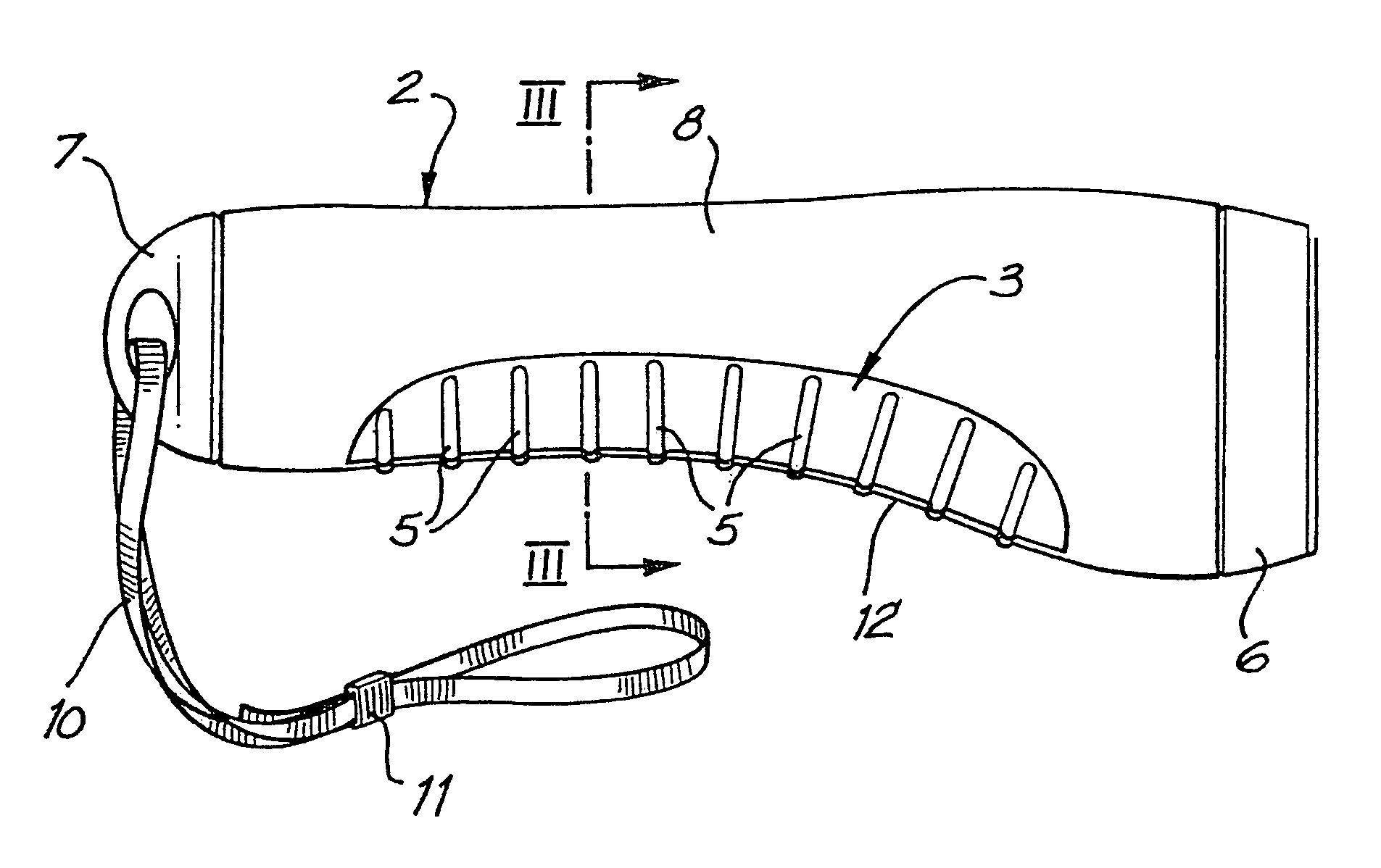
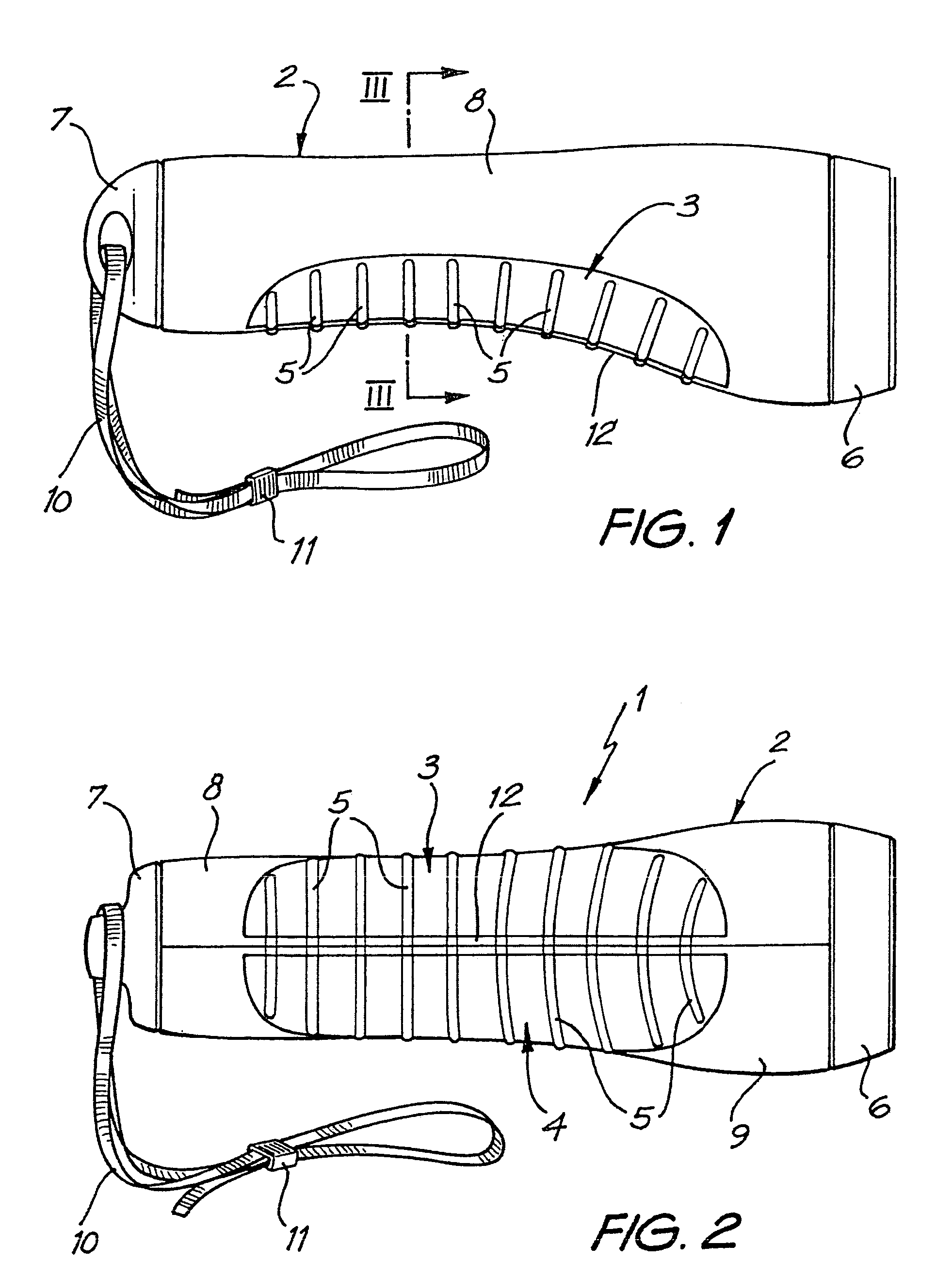
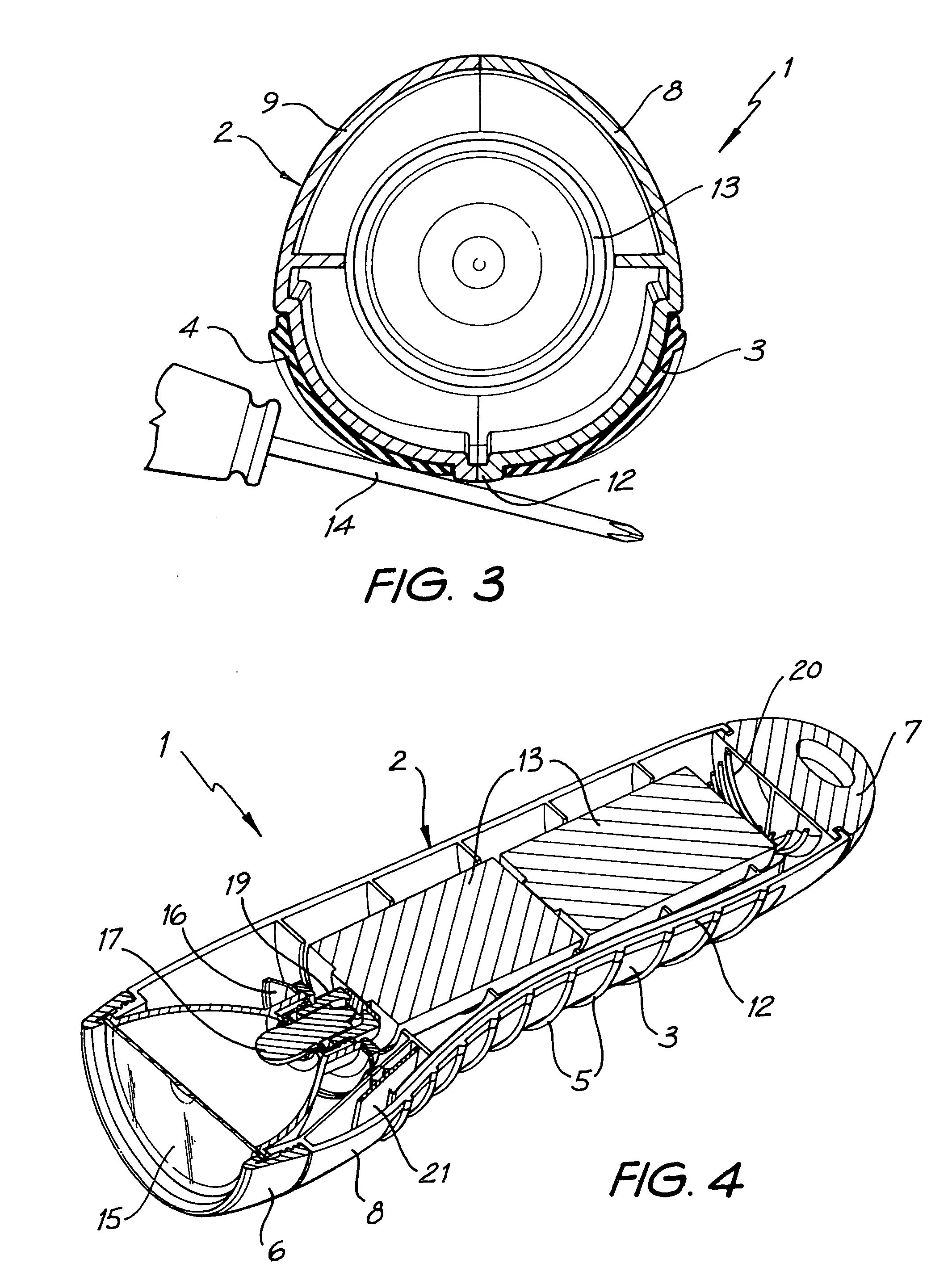
[0063]Referring to the figures, the preferred embodiment of the present invention is depicted in flashlight 1, which comprises non-conductive housing 2, batteries 13, light bulb 17, and first and second nodes 3 and 4. Non-conductive housing 2 provides the body of flashlight 1 and comprises lens ring 6, first and second side portions 8 and 9, rib 12, and end cap 7. First and second nodes 3 and 4 are disposed adjacent to and on either side of rib 12. When first and second nodes 3 and 4 are electrically bridged, electric current is allowed to flow from batteries 13 through light bulb 17, thereby activating flashlight 1. In use, first and second nodes 3 and 4 are electrically bridged by a user's hand when the user grasps flashlight 1. The protrusion provided by Rib 12 minimizes inadvertent activation of flashlight 1 by preventing linear portions of conductive objects like screwdrivers and the like from simultaneously contacting both first and second nodes 3 and 4.

[0064]First and second ...


PUM


Abstract

A flashlight having a non-conductive housing, an electric power source, a light source, and two nodes disposed on external surfaces of the non-conductive housing, wherein the flashlight is adapted to allow electric current to flow from the power source through the light source when both of the two nodes are abutted by a user's hand, activating the flashlight without further manipulation required by the user. Inadvertent activation of the flashlight is minimized by including a protruding rib between the nodes or by disposing the nodes on different sides of the flashlight.

Description

BACKGROUND OF THE INVENTION[0001]1. Field of the Invention[0002]The present invention relates to portable lighting devices such as floodlights, flashlights, key-chain lights and laser pointers and in particular relates to portable lighting devices having touch sensitive activation. While the present invention relates to all portable lighting devices, reference will be made throughout this specification to the preferred embodiment of a flashlight by way of example only.[0003]2. Prior Art[0004]It is known in the art to use manual switches such as pushbuttons, sliding switches, and the like to turn flashlights on and off. Since their inception, flashlights have incorporated manual switches that require manipulation by the user's fingers. In recent years, flashlights and other lights have been developed in the art to create touch sensitive “switches” from exposed terminals of an open circuit intended to be electrically bridged through the conductive medium of some portion of a user's bo...

Claims


Application Information

Patent Timeline
Patent Type & Authority Patents(United States)
IPC IPC(8): F21L4/04F21V23/04
CPCF21V23/0414F21V21/406
Inventor ABEL, JEREMY AARONDEB, SATYAJITMCKEON, THOMAS MICHAELSCHENNUM, STEVEN MICHAELWHITE, CRAIG ALLEN
Owner CREATA MACAO COMML OFFSHORE
Why Eureka
Try Eureka