Near-Field Miniature Coupler

a near-field, coupler technology, applied in the direction of mechanical actuation of burglar alarms, instruments, pulse techniques, etc., can solve the problems of inability to increase system complexity, cost, etc., to minimize the footprint of the coupler, minimize the inadvertent activation, and control the coupling range

Active Publication Date: 2008-10-02
ZEBRA TECH CORP
View PDF30 Cites 28 Cited by
  • Summary
  • Abstract
  • Description
  • Claims
  • Application Information

AI Technical Summary

Benefits of technology

[0010]The present invention may address some of the above needs by providing a near-field coupler for a RFID system configured to selectively communicate with a targeted transponder from among a group of adjacent transponders. The coupler is adapted to have a controlled coupling range that can be limited to minimize the inadvertent activation of transponders outside a transponder encoding region. As such, the coupler operates with little to no collision management techniques or shielding components. The coupler of the present invention is compact, usually one-quarter wavelength or less of a center operating frequency within the UHF band. This compact design minimizes the footprint of the coupler within the space-restricted RFID system. Moreover, the coupler's smaller size relative to the transponder allows for an optimal alignment between the coupler and transponder during the encoding process.

Problems solved by technology

Problems can occur when interrogating multiple adjacent transponders regardless on whether the transponders are passively or actively powered.
This simultaneous activation of multiple transponders may lead to collision errors because each of the multiple transponders may transmit reply signals to the transceiver at the same time.
However, such collision management techniques tend to increase system complexity, cost, and delay response.
Furthermore, such techniques are often “blind” in that they cannot locate a given transponder or more specifically recognize the position of a transponder within the interrogating RF electromagnetic field.
Unfortunately, RF-shielded housings add cost and complexity to a system and limit the type (i.e., the size) of transponders they may be processed by the system.
Furthermore, many devices are limited with regard to space or weight and, thus, cannot accommodate such shielded housings.
The close proximity of the transponders to each other, during processing, makes single transponder activation problematic.
Moreover, the space, cost, and weight restrictions associated with such devices, among other factors, make collision management techniques or shielding components for alleviating multiple transponder activation less than desirable.

Method used


Image

  • Near-Field Miniature Coupler
  • Near-Field Miniature Coupler
  • Near-Field Miniature Coupler

Examples


Embodiment Construction

[0020]The present invention now will be described more fully hereinafter with reference to the accompanying drawings, in which some, but not all embodiments of the invention are shown. Indeed, this invention may be embodied in many different forms and should not be construed as limited to the embodiments set forth herein; rather, these embodiments are provided so that this disclosure will satisfy applicable legal requirements. Like numbers refer to like elements throughout.

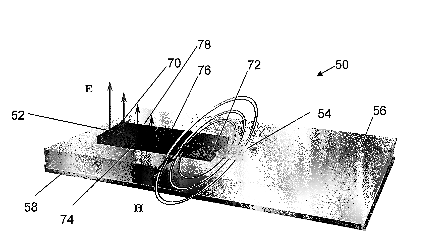
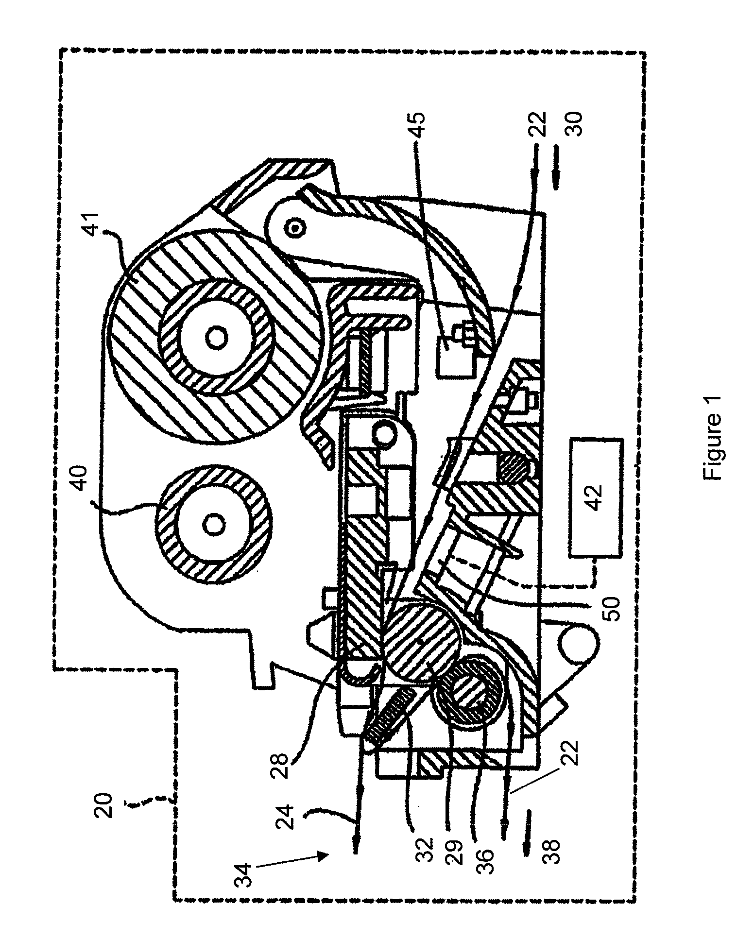
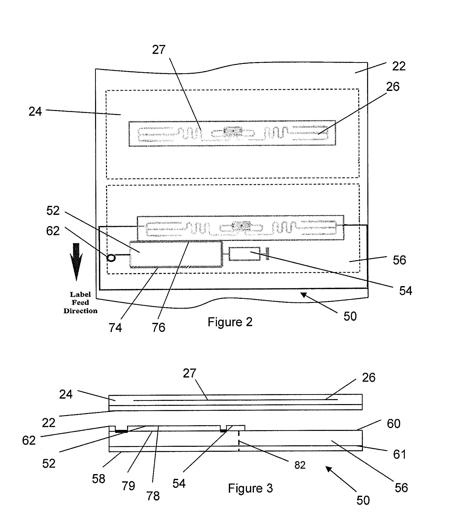
[0021]The present invention concerns an apparatus for enabling an RFID transceiver (sometimes referred to as a “reader”) to selectively communicate with a targeted transponder that is commingled among or positioned in proximity to multiple adjacent transponders. As will be apparent to one of ordinary skill in the art, various embodiments of the present invention are described below that selectively communicate with a targeted transponder without requiring physical isolation of the transponder using space-consuming...


PUM


Abstract

A near-field coupler for a RFID system is provided. The coupler is configured to selectively communicate with a targeted transponder from among a group of multiple adjacent transponders. The coupler includes a conductive strip terminated by a load. The load is for matching an input impedance of the coupler to a source impedance of a transceiver. The conductive strip is based on a quarter wavelength of the center operating frequency. The conductive strip may have a substantially constant width and a length substantially equal to the quarter wavelength. Or the conductive strip may have a variable width defining a tapered profile and a length less than the quarter wavelength. The tapered profile may be an exponential profile or a Klopfenstein profile. Due to the overall size of the coupler to a typical transponder, the center of the coupler and the center of the transponder may be offset during coupling.

Description

BACKGROUND OF THE INVENTION[0001]1. Field of the Invention[0002]The present invention relates to RFID couplers and, in particularly, to spatially selective couplers capable of selectively communicating with a targeted transponder from among a group of adjacent transponders.[0003]2. Description of Related Art[0004]Radio frequency identification (RFID) transponders, either active or passive, are typically used with an RFID transceiver or similar device for communicating information back and forth. In order to communicate, the transceiver exposes the transponder to a radio frequency (RF) electromagnetic field or signal. In the case of a passive UHF transponder, the RF electromagnetic field energizes the transponder and thereby prompts the transponder to respond to the transceiver by re-radiating the received signal and modulating it in a well-known technique called backscattering. In the case of an active transponder, the transponder may respond to the electromagnetic field by transmit...

Claims


Application Information

Patent Timeline
Patent Type & Authority Applications(United States)
IPC IPC(8): H04Q3/06
CPCG06K7/0008G06K7/10237G06K19/07749H04Q2213/13093
Inventor TSIRLINE, BORIS Y.TORCHALSKI, KARLSCHWAN, MARTIN ANDREAS KARL
Owner ZEBRA TECH CORP
Why Eureka
Try Eureka