Apparatus and methods for utilizing a downhole deployment valve

a technology of deployment valve and deployment valve, which is applied in the direction of borehole/well accessories, tubing catchers, survey, etc., can solve problems such as damage to valve members

Inactive Publication Date: 2007-02-20
WEATHERFORD TECH HLDG LLC
View PDF59 Cites 76 Cited by
  • Summary
  • Abstract
  • Description
  • Claims
  • Application Information

AI Technical Summary

Problems solved by technology

Once actuated, the barrier or diverter either stops or diverts any dropped obj...

Method used


Image

  • Apparatus and methods for utilizing a downhole deployment valve
  • Apparatus and methods for utilizing a downhole deployment valve
  • Apparatus and methods for utilizing a downhole deployment valve

Examples


Embodiment Construction

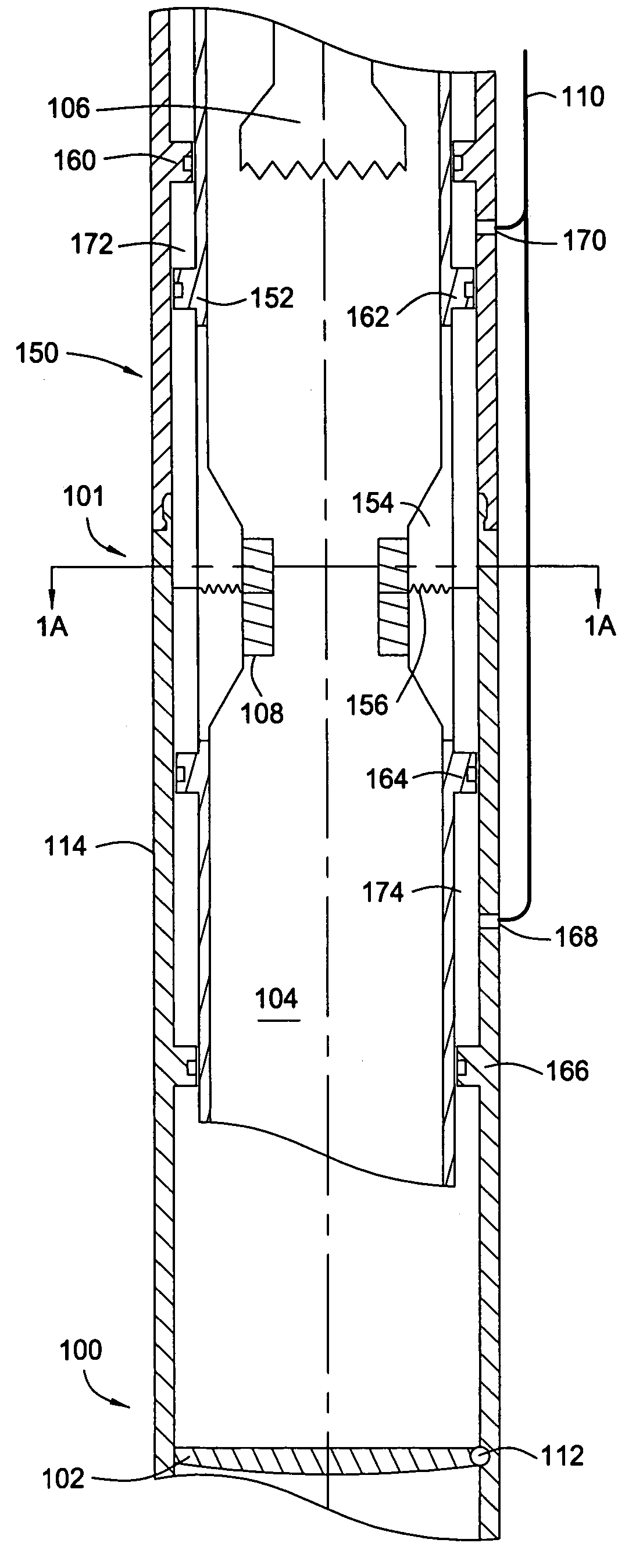
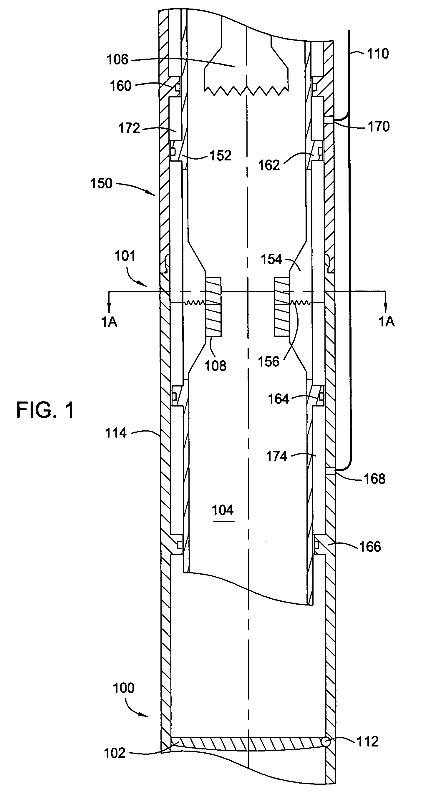
[0022]The invention generally relates to methods and apparatus for utilizing a downhole deployment valve (DDV) in a wellbore. The DDV may be any type of valve such as a flapper valve or ball valve. Additionally, any type of actuation mechanism may be used to operate the DDV. For example, the DDV may actuate between an open and closed position by fluid pressure or electric current supplied from a control line.

[0023]FIG. 1 illustrates a section view of a DDV 100 in a closed position with a barrier assembly 101 in an extended position. The barrier assembly 101 and the DDV 100 are disposed in casing, and the barrier assembly 101 may be an integral part of the DDV 100 or a separate component. As shown, a flapper 102 of the DDV 100 rotates about pivot 112 to seal a bore 104 passing through the DDV 100, thereby isolating the formation pressure below the flapper 102 from the bore 104 above the flapper 102. A tool string 106 is tripped into the bore 104 while the DDV 100 is in the closed pos...


PUM


Abstract

Methods and apparatus for utilizing a downhole deployment valve (DDV) to isolate a pressure in a portion of a bore are disclosed. Any combination of fail safe features may be used with or incorporated into the DDV such as redundant valve members, an upward opening flapper valve or a metering flapper below a sealing valve. In one aspect, a barrier or diverter located in the bore above a valve member of the DDV permits passage through the bore when the valve member is open and actuates when the valve member is closed. Once actuated, the barrier or diverter either stops or diverts any dropped objects prior to the dropped object reaching and potentially damaging the valve member. In another aspect, the tool string tripped in above the DDV includes an acceleration actuated brake that anchors the tool string to a surrounding tubular if the tool string is dropped.

Description

CROSS-REFERENCE TO RELATED APPLICATIONS[0001]This application is a continuation-in-part of co-pending U.S. patent application Ser. No. 10 / 677,135, filed Oct. 1, 2003, which is a continuation in part of U.S. patent application Ser. No. 10 / 288,229, filed Nov. 5, 2002, which are herein incorporated by reference in their entirety. This application is a continuation-in-part of co-pending U.S. patent application Ser. No. 10 / 676,376, filed Oct. 1, 2003, which is a continuation in part of U.S. patent application Ser. No. 10 / 288,229, filed Nov. 5, 2002, which are herein incorporated by reference in their entirety. This application claims benefit of U.S. Provisional Patent Application Ser. No. 60 / 485,816, filed Jul. 9, 2003, which is herein incorporated by reference in its entirety.BACKGROUND OF THE INVENTION[0002]1. Field of the Invention[0003]Embodiments of the invention generally relate to methods and apparatus for use in oil and gas wellbores. More particularly, the invention relates to m...

Claims


Application Information

Patent Timeline
IPC IPC(8): E21B34/10E21B21/00E21B21/08E21B21/10E21B33/04E21B33/10E21B34/00E21B34/06E21B34/08E21B34/12E21B34/14E21B34/16E21B40/00E21B41/00E21B43/00E21B47/01E21B47/09E21B47/10E21B47/12
CPCE21B21/08E21B33/0407E21B34/06E21B34/101E21B34/14E21B34/16E21B41/0021E21B47/01E21B47/09E21B47/10E21B47/12E21B47/122E21B21/103E21B2034/005E21B2021/006E21B21/085E21B2200/05E21B47/13E21B34/142E21B41/00E21B43/00
Inventor LUKE, MIKE A.FULLER, TOMJOHNSON, DARRELLBRUNNERT, DAVIDGRAYSON, BRIANPAVEL, DAVIDBANSAL, R. K.
Owner WEATHERFORD TECH HLDG LLC
Why Eureka
Try Eureka