

Ion source with substantially planar design
a planar design and ion source technology, applied in the direction of ion beam tubes, electric discharge lamps, instruments, etc., can solve the problems of adversely affecting the electric field potential between, adversely affecting the operability and/or efficiency of the ion source, etc., to achieve less undesirable build-up and source run more efficiently
- Summary
- Abstract
- Description
- Claims
- Application Information
AI Technical Summary
Benefits of technology
Problems solved by technology
Method used
Image

Examples
Embodiment Construction
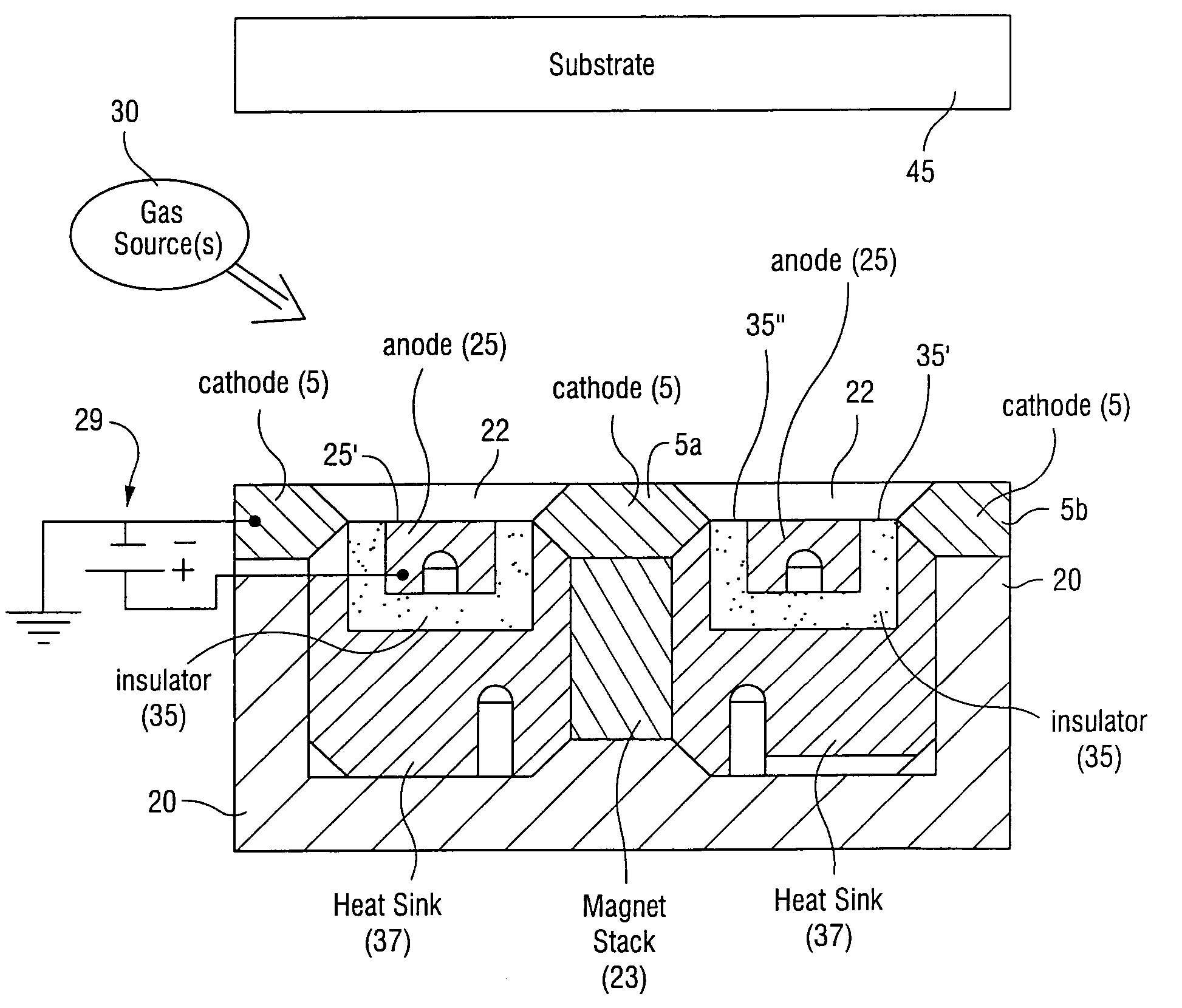
[0013]In certain example embodiments of this invention, there is provided an ion source including an anode and a cathode. In certain example embodiments, the cathode does not substantially overhang over the anode, or vice versa. Since no, or fewer, areas of overhang are provided between the anode and cathode, there is less undesirable build-up on the anode and / or cathode during operation of the ion source so that the source can run more efficiently. Moreover, in certain example embodiments, an insulator such as a ceramic or the like is provided between the anode and cathode.
[0014]In certain example embodiments of this invention this substantially planar design, where there is no area of overhang between the anode / cathode on the side of the ion source facing the substrate, is advantageous in that: (a) it permits high current operation at low potential thereby yielding a high flux of potentially low energy ions toward the substrate; (b) the lack or reduction of overhang areas or inter...
PUM
 Abstract
Description
Claims
Application Information