Cabinet door knob pull measuring jig

a technology for measuring jigs and cabinet doors, applied in the field of measuring jigs, can solve the problems of time-consuming methods, more difficult than one realizes, and pain in the cabinet door, and achieve the effect of quick identification, accurate and precise manner

Inactive Publication Date: 2007-03-13
MIRO ANTHONY W
View PDF31 Cites 7 Cited by
  • Summary
  • Abstract
  • Description
  • Claims
  • Application Information

AI Technical Summary

Benefits of technology

[0008]The primary object of the present invention is to provide a cabinet door knob pull measuring jig that allows a person to quickly identify the location of a hole to be drilled on a cabinet door for a knob pull in an accurate and precise manner.
[0009]A further object of the present invention is to provide a cabinet door knob pull measuring jig that is versatile.
[0010]An even further object of the present invention is to provide a cabinet door knob pull measuring jig that is lightweight.

Problems solved by technology

Although drilling holes into a cabinet door for the knob pulls may seem like a simple task, it is more difficult than one realizes.
Not only is this method time-consuming, but if a measurement is slightly off, the resulting cabinet door is a painful eyesore as the knobs do not line-up appropriately and may require the cabinet door to be replaced.
Although there currently exist a wide range of measuring jigs which attempt to quickly and accurately measure the location for a knob pull hole, the jigs are either too cumbersome for quick use, not versatile enough to use on a wide variety of cabinet sizes, not durable enough for heavy use or simply too large in size for easy portability.

Method used


Image

  • Cabinet door knob pull measuring jig
  • Cabinet door knob pull measuring jig
  • Cabinet door knob pull measuring jig

Examples


first embodiment

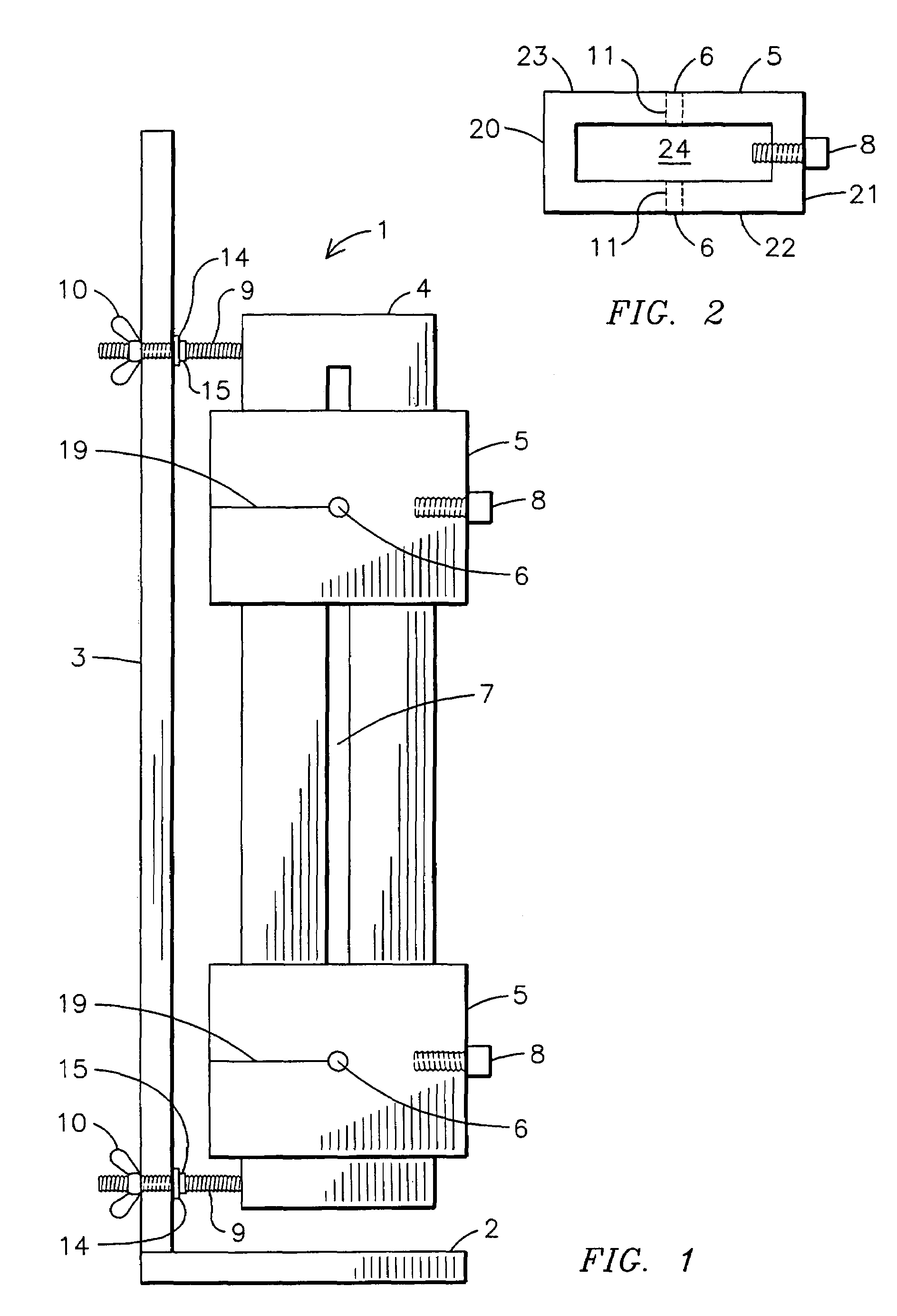
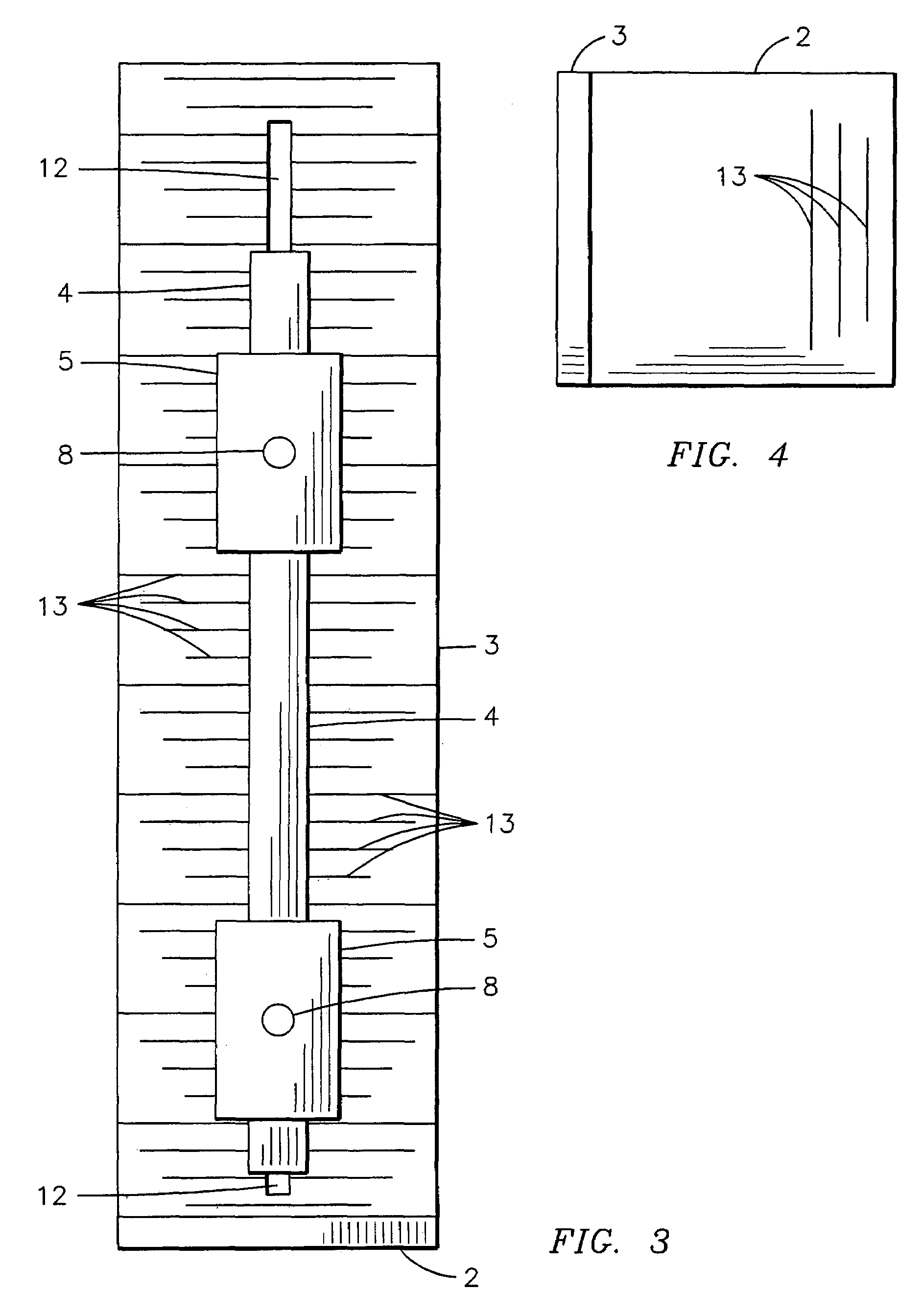
[0025]With reference to FIG. 1, a side plan view of the present invention is shown. The door knob pull measuring jig 1 includes a baseboard 2 and a backboard 3 attached to one another perpendicularly. A drilling plate 4 having a drilling plate slot 7 is adjustably secured to the backboard 3 via screws 9 extending from the drilling plate 4 and wingnuts 10. Washers 14 and nuts 15 are located on the screws 9 so as to assist in the positioning and holding of the drilling plate 4. At least one sliding block 5 is adjustably secured to the drilling plate 4. The sliding bock 5 includes at least one pilot hole 6 positioned in vertical alignment with the drilling plate slot 7. At least one thumbscrew 8 is located on the sliding block 5 for tightening the sliding block 5 on the drilling plate 4. Line-up markings 19 are located adjacent to the pilot holes 6.

[0026]With reference to FIG. 2, a top view of a sliding block 5 of a first embodiment of the present invention is shown. The sliding block ...

second embodiment

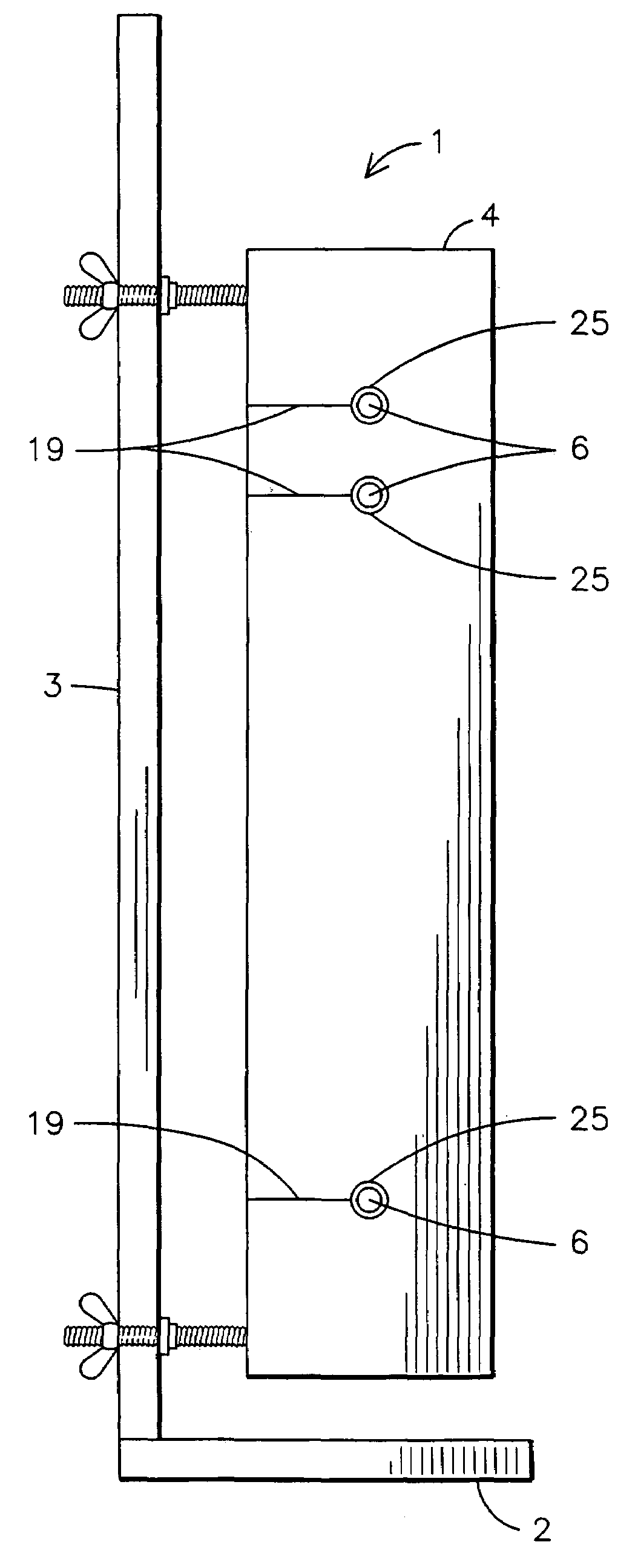
[0030]Finally, FIG. 6 is a side view of a second embodiment of the present invention. Similar to the first embodiment, the door knob pull measuring jig 1 of the present invention includes a frame having a baseboard 2 and a backboard 3 wherein the backboard 3 has a backboard slot 12. However, the adjustable drilling plate 4 of the second embodiment does not include a drilling plate slot as in the first embodiment and does not include sliding blocks 5. Rather, the drilling plate 4 of the second embodiment has pilot holes 6 and line-up markings 19 located directly on the drilling plate 4. The second embodiment, as well as the first embodiment, may also include steel bushings 25 in the pilot holes 6 so as to allow for a longer-lasting and more durable door knob pull measuring jig 1. Because the backboard slot 12 is located on the backboard 3 and the backboard 3 and baseboard 2 form a true L-shape, the drilling plate 4 may extend beyond the backboard 3 when in use.

[0031]The use of the pr...


PUM

PropertyMeasurementUnit
L-shapeaaaaaaaaaa
vertical distancesaaaaaaaaaa
sizesaaaaaaaaaa

Abstract

A cabinet door knob pull measuring jig (1) comprising a frame having a baseboard (2) and a backboard (3) which are connected together to form an L-shape, a drilling plate (4) adjustably attached within a vertical slot (12) located in the backboard (3) and at least one sliding block (5) adjustably attached to a vertical slot (7) located in the drilling plate (4). At least one pilot hole (6) is located in the at least one sliding block (5). A second embodiment of the measuring jig (1) utilizes the same baseboard (2) and backboard (3). However, rather than using at least one sliding block (5), the drilling plate (4) itself has at least one pilot hole (6) located thereon. The use of the present invention will permit a person to quickly identify the location of a hole to be drilled on a cabinet door for a knob pull in an accurate and precise manner.

Description

BACKGROUND OF THE INVENTION[0001]This invention relates to measuring jigs, more particularly, a cabinet door knob pull measuring jig that permits a person to quickly identify the location of a hole to be drilled on a cabinet door for a knob pull in an accurate and precise manner.[0002]Many cabinet manufacturers do not include holes in the cabinet doors for a variety of reasons. For instance, customers prefer to personalize the cabinet door by selecting his or her own knob pulls, which vary in hole locations. In addition, in order to further customize the cabinet door, customers select the location of the knob pulls, which are also known as jewelry, on the cabinet door. Although drilling holes into a cabinet door for the knob pulls may seem like a simple task, it is more difficult than one realizes.[0003]Accurate measuring is an essential step when drilling holes for knob pulls. Currently, many cabinet installers or do-it-yourselfers use a standard tape measure to measure the horizon...

Claims


Application Information

Patent Timeline
Patent Type & Authority Patents(United States)
IPC IPC(8): B23B47/28
CPCB23B47/287E05B17/06B23B2247/06B23B2260/004Y10T408/56245Y10T408/567B23B2260/088
Inventor MIRO, ANTHONY W.
Owner MIRO ANTHONY W
Why Eureka
Try Eureka