Drawer know pull measuring jig

a technology of measuring jigs and drawers, which is applied in the field of measuring jigs, can solve the problems of time-consuming methods, drawers are painful eyesores, and the difficulty of identifying, and achieve the effect of quick identification, accurate and precise manner

Inactive Publication Date: 2007-05-10
MIRO ANTHONY W
View PDF21 Cites 21 Cited by
  • Summary
  • Abstract
  • Description
  • Claims
  • Application Information

AI Technical Summary

Benefits of technology

[0007] The primary object of the present invention is to provide a drawer knob pull measuring jig that allows a person to quickly identify the location of a hole to be drilled on a drawer face for a knob pull in an accurate and precise manner.

Problems solved by technology

Although drilling holes into a drawer for the knob pulls may seem like a simple task, it is more difficult than one realizes.
Not only is this method time-consuming, but if a measurement is slightly off, the resulting drawer is a painful eyesore as the knobs do not line-up appropriately and may require the drawer to be replaced.
Although there currently exists a wide range of measuring jigs which attempt to quickly and accurately measure the location for a knob pull hole, the jigs are flawed for several reasons.
In addition, the current jigs are either too cumbersome for quick use, not versatile enough to use on a wide variety of drawer sizes, not durable enough for heavy use, clamp onto the drawer faces, which is time consuming or are simply too large in size for easy portability.

Method used


Image

  • Drawer know pull measuring jig
  • Drawer know pull measuring jig
  • Drawer know pull measuring jig

Examples


first embodiment

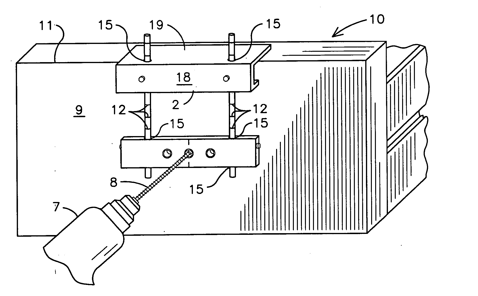
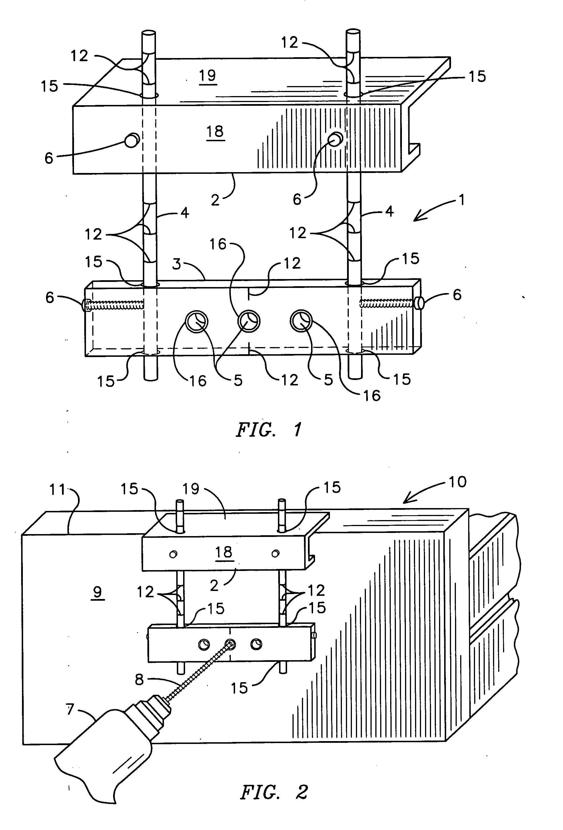
[0025] With reference to FIGS. 1 and 2, varying views of a drawer knob pull measuring jig of the present invention is shown. The drawer knob pull measuring jig 1 includes a suspension plate 2 having a vertical side 18 and a horizontal side 19 wherein the suspension plate 2 is secured to a drill plate 3 via at least one pole 4. The poles 4 are inserted through apertures for poles 15 located on both the horizontal side 19 of the suspension plate 2 and the drill plate 3. The poles 4 are secured to the plates 2 and 3 via thumb screws 6. The suspension plate 2 is preferably J-shaped so as to permit a user to position the suspension plate 2 such that it is suspended from the drawer top face edge 11 and allows the drill plate 3 to be flush against a drawer 10. However, the suspension plate 2 may also be L-shaped or C-shaped, so long as the suspension plate 2 includes a vertical side 18 and a horizontal side 19 that is sufficiently wide to extend over a top of a drawer face 11. Markings 12 ...

second embodiment

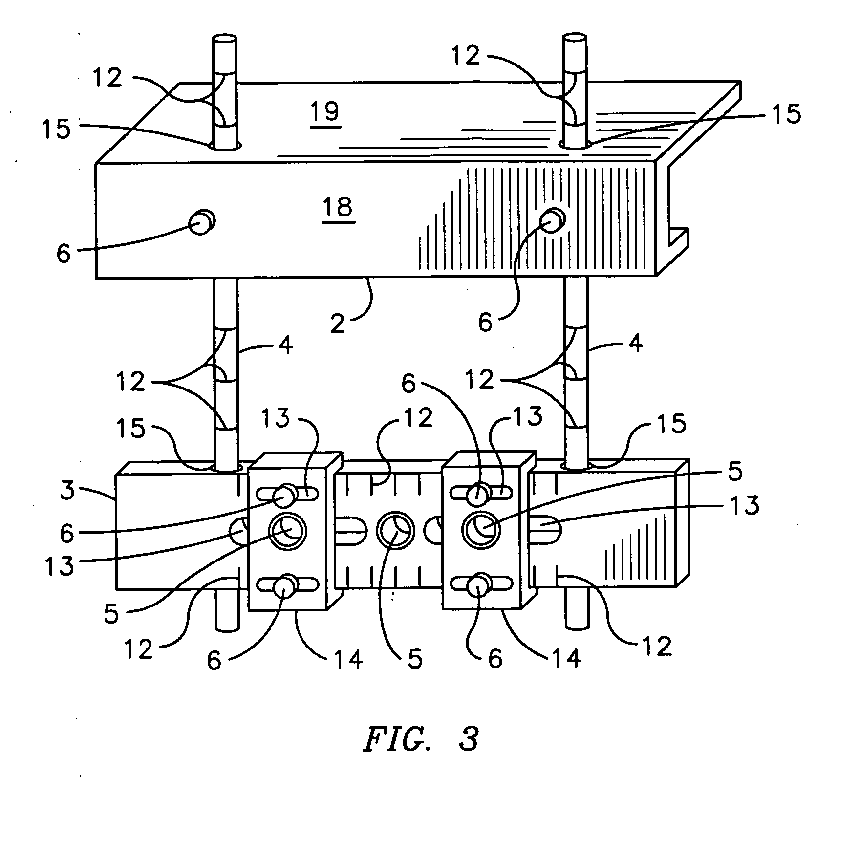
[0032] At least one sliding block 14 is positioned on the drill plate 3 so as to permit adjustable pilot holes 5. The sliding block 14 includes at least one slot 13 and at least one pilot hole 5. To use the present invention, a user measures the distance from one side edge of a drawer 10 and adjusts the drill plate 3 and / or suspension plate 2 via sliding the drill plate 3 up and down along the poles 4 and tightening the thumb screws 6 on the suspension plate 2. Then, the user adjusts the sliding blocks 14 horizontally along the drill plate 3 such that the pilot holes 5 on the sliding blocks 14 are in the desired position in front of the drawer face 9. The user then tightens the thumb screws 6 that are inserted through the slots 13 on the sliding blocks 14 and into the apertures for thumb screws 17 located on the drill plate 3. Because the diameter of the slots 13 on the sliding blocks 14 are smaller than the diameter of the thumb screws 6, when the thumb screws are tightened against...


PUM


Abstract

A drawer knob pull measuring jig (1) comprising a suspension plate (2) and a drill plate (3) adjustably secured to one another via at least one pole (4). At least one pilot hole (5) is located in the drill plate (3). A second embodiment of the measuring jig (1) has at least one sliding block (14) is located on the drill plate (3) so as to permit a user to adjustably select the distances between pilot holes (5). The use of the present invention will permit a person to quickly identify the location of a hole to be drilled on a drawer face (9) for a knob pull in an accurate and precise manner.

Description

BACKGROUND OF THE INVENTION [0001] This invention relates to measuring jigs, more particularly, a drawer knob pull measuring jig that permits a person to quickly identify the location of a hole to be drilled on a drawer for a knob pull in an accurate and precise manner. [0002] Many drawer manufacturers do not include holes in the drawer face for a variety of reasons. For instance, customers prefer to personalize the drawer face by selecting his or her own knob pulls, which vary in hole locations. In addition, in order to further customize the drawer, customers select the location of the knob pulls, which are also known as jewelry, on the drawer face. Although drilling holes into a drawer for the knob pulls may seem like a simple task, it is more difficult than one realizes. [0003] Accurate measuring is an essential step when drilling holes for knob pulls. Currently, many drawer installers or do-it-yourselfers use a standard tape measure to measure the horizontal and vertical distanc...

Claims


Application Information

Patent Timeline
Patent Type & Authority Applications(United States)
IPC IPC(8): B25H7/00
CPCB23B47/287B23B2260/088
Inventor MIRO, ANTHONY W.
Owner MIRO ANTHONY W
Why Eureka
Try Eureka